Hi Alex,
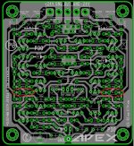
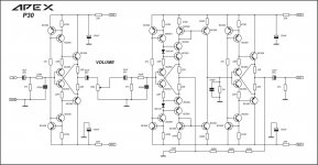
I'm testing but have some issues. Before I tackle all of them, could you please look at the pot wiring and let me know if I am looking at it right? If I am reading the schematic correctly, one outer leg of the pot comes from the front end and the other outer leg goes to ground. Then the sweep goes on to the input of the second half. It appears that on your board the center pin is not the sweep. Am I reading that correctly?
Thanks, Terry
I am also attaching an asc file I created. It runs but not right. Maybe someone could take a look and see if you can find my error(s).
Thanks, Terry
Attachments

Hi Alex,
I'm testing but have some issues. Before I tackle all of them, could you please look at the pot wiring and let me know if I am looking at it right? If I am reading the schematic correctly, one outer leg of the pot comes from the front end and the other outer leg goes to ground. Then the sweep goes on to the input of the second half. It appears that on your board the center pin is not the sweep. Am I reading that correctly?
Thanks, Terry
I am also attaching an asc file I created. It runs but not right. Maybe someone could take a look and see if you can find my error(s).
Thanks, Terry
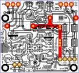
The center pin it's connected to the ground ,the rest you know .
In your simulation forget in LT schematic to include two resistors 22 ohms at rail voltage .... see picture attached .
Best regards,Alex
Attachments

The center pin it's connected to the ground ,the rest you know .
In your simulation forget in LT schematic to include two resistors 22 ohms at rail voltage .... see picture attached .
Best regards,Alex
The center pin it's connected to the ground
But it isn't according to published schematic.
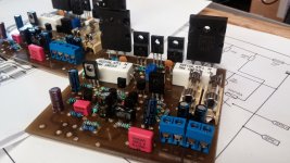
so that's my next project with Apex amp ... after few problems with SKA I decided replaced SKA by Apex....😀
oh nice ... sir 🙂 you cut the board, the other day I was thinking to make smaller size PCB of the AX-14 it does look great sir
Regards
Juan
Attachments
yes, i have to fit the boards it into my chassis..BTW you added some 10R resistors, which are not in schematic 🙂.... from my experience I little bit decrease gain, from my point of view it was too high ....
oh ok I see ... so the 10R is not necessary ? Terry build it with the 10R there maybe he can comment something about " I do not mind to removed if not necessary"  uhmmm any way what the heck we are not perfect jejejeje 😛
Regards
Juan
uhmmm any way what the heck we are not perfect jejejeje 😛Regards
Juan
Last edited:
The center pin it's connected to the ground
But it isn't according to published schematic.
As far as the pot will not lay on the board, it is simply a case of twisting wires. 😎
As far as the pot will not lay on the board, it is simply a case of twisting wires. 😎
Yes, I knew that but I wanted to be sure that I was reading the schematic correctly. I was getting a bad offset and I'm hoping that is why. I'll rewire it and test again.
Thanks, Terry
The center pin it's connected to the ground ,the rest you know .
In your simulation forget in LT schematic to include two resistors 22 ohms at rail voltage .... see picture attached .
Best regards,Alex
Hi Alex,
I will change the wiring on the pot to match your layout. Others who want to build this should be aware of this. Maybe if you get some time you might want to change that so the center pin is the sweep. It would save on confusion.
Thanks for looking at the spice file. I did have the 22R resistors. They are all the way to the right near the voltage sources like in the schematic. However, Q11 & D2 were mislabeled, and the bridge was missing at Q17. I have repaired them and it runs better but still not perfect. I am attaching the corrected file. Maybe you or one of the other Ltspice gurus can take a look.
Blessings, Terry
Attachments
Hi Alex,
I will change the wiring on the pot to match your layout. Others who want to build this should be aware of this. Maybe if you get some time you might want to change that so the center pin is the sweep. It would save on confusion.
Blessings, Terry
It will be hard to do that because the two electrolytic capacitor.
Is not impossible but that would increase the size if the PC boards.
Alex did a great job as always!!!🙂
If you use wires to connect the pot I think the layout is perfect just need some notice or warning about the pot connection.
Greetings
I didn't mean to insult the layout. I did mention that folks should be made aware of the layout. The only bad thing about that pin configuration is that the pot has to be wired the right way or the pot can be reverse acting. With the sweeper pin in the center the plug only has to be reversed. You both know layout waaaaay better than me, so if you say it is difficult to change I will take your word for it.
I'm having big issues with my boards right now. That is why I wanted to get the asc working properly so I will have a basis to troubleshoot from. Since I am the first to build this others can't help me. I need a reference so hope to use the spice file. I can't even seem to get that right and I think it now mimics the original schematic. Alex added a few caps that aren't on the schematic but those shouldn't be causing any issues. I tested all the transistors before I installed them and have triple checked that they are correct. They test good with a diode test now that they are installed as well so I will keep digging. I am hopeful I can get it working as it looks like a cool concept.
Blessings, Terry
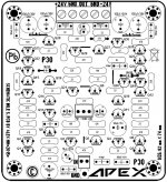
Wow, this has been journey. Through building the asc file I gave each part a number. Then started transferring the part numbers to the silk. If I am correct Q15 and Q19 are inverted. Would someone please give it a look-see?
Thanks, Terry
Thanks, Terry
Attachments

Last edited:
I fixed the spice file, sort of. I have all the correct devices, resistors and caps where they go. I runs clean but the output is very low. I'm attaching it. I'm not sure if Mile uses Ltspice but hopefully he can explain what I'm seeing.
Thanks, Terry
Thanks, Terry
Attachments
Wow, this has been journey. Through building the asc file I gave each part a number. Then started transferring the part numbers to the silk. If I am correct Q15 and Q19 are inverted. Would someone please give it a look-see?
Thanks, Terry
No , you are not correct Q15 and Q19 are not inverted 😉
Regards,Alex
Did you only read that one post? I explained in post 4595. This is a tough one to get working. Even the spice file is not working like it should. Hopefully we can get it ironed out. I have a lot of parts invested.
Blessings, Terry
Blessings, Terry
..............If I am correct Q15 and Q19 are inverted. Would someone please give it a look-see?...........
Please disregard, R15 and R19 are correct. ..............
No , you are not correct Q15 and Q19 are not inverted..............
R & Q are not the same.Did you only read that one post? I explained in post 4595. .............
Sorry about all this. I am just trying to get the circuit working. After scouring the boards and measuring every component I decided to try building a spice file to give me a basis to work from. I made some mistakes in the file at first that caused me some problems. Now I have the file working but the circuit doesn't seem to work. I don't want to make any more changes to the boards until the circuit is at least proved in ltspice. Home etched boards don't take too many changes without damaged traces.
Thanks, Terry
Thanks, Terry
- Home
- Amplifiers
- Solid State
- 100W Ultimate Fidelity Amplifier