Member
Joined 2009
Paid Member
I have been THINKING about this !!!
I remember introducing this to you here 😀
http://www.diyaudio.com/forums/tubes-valves/221739-nice-little-valve-amplifier.html
Where can I systematically go on line to LEARN how to do this, easily, OR, is there ANY way you, or someone else can personally can show me the way to do the math??
Loftin White: ECC83 als Treiber für die 300B, Bestimmung einer Kennzahl
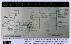
There are only two calculations that are specific to this design. The first (middle of the page) is the "triode factor". Simply put, this is the ratio of the plate resistor, divided by the resistance of the tube at the plate. This ratio should be greater than 4 for good linearity. Note that this must be calculated from the actual values at the chosen operating point (not from the "characteristics and typical operation" shown on the tube data sheet, but from the "average characteristics" graph)
http://www.mif.pg.gda.pl/homepages/frank/sheets/093/1/12AX7.pdf
The second calculation, near the bottom of the page, shows how to calculate the plate load impedance (which is your load line) when adding the bootstrapped follower. You can skip this one, if you use values reasonably similar to those shown.
You will see by doing a few calculations of the "triode factor" that only a few combinations will work without the follower to provide sufficient current for extended frequency response - at least by normal standards (I know you differ on this). The follower makes the question of frequency response for low current input tubes moot.
Otherwise your output tube operating point is whatever you prefer. Look at soulmerchant's schema for how to set up the PS noise cancelation. This calculation is simple: The cathode to cathode resistance string, divided by the input cathode value, should be equal to the u of the input tube. The actual optimal value is determined by adjusting by ear, around the calculated value, and will vary some from tube to tube.
Sheldon

I remember introducing this to you here 😀
http://www.diyaudio.com/forums/tubes-valves/221739-nice-little-valve-amplifier.html
OK, I just re-read your thread with a new and better attitude. SO, you have a PhD in Physics, very good !!! No wonder people didn't sway you easily.
I have developed TWO thoughts since posting this weekend, and reading up on this subject so far :
(1) I do NOT want to add any third stage in a clever Darius bootstrap, because I want all my amps to be a transparent sounding / simple ( KISS ) TWO stage amps.
( No cathode followers for me please, despite "theory". There are simpler ways to proceed. )
However, I AM now very much interested in applying hum cancellation, IF I can get a handle on it and learn how to implement it.
(2) I do NOT want to run my Finals stage B+ and my Input stage B+ from the same COMMON filtered supply. By that, I mean I want to R/C decouple my Input stage, to get low ripple ( 1 to 2 mVAC ) and I want to have LOW DCR magnetic parts, Ls under 10 Ohms and no caps over 50 uF, in the filter to the Finals, so that I can maintain a fast and high peak current capability supply ( I will tolerate B+ ripple up to 850 mVAC to 2A3 Finals, OK on ALE drivers !!! ).
If I do not SOMEHOW decouple the two filter topologies, there is NO WAY with a COMMON B+ filter to optimize either !!! Presently, I use : L1/C1/L2/C2 ( Finals ) R1/C1 ( Input ) with success.
- - - - - - - - - - - - - - - - - - - - - - - - - - -
What are you doing with all those parts? Have you commenced a build?
I presently have all THREE of my DC amps apart, waiting to be rebuilt with newer parts and ideas. I have some audio subjects I would like to discuss with you, and some parts you would probably use, on a eBay seller's very current auction.
Could you email me privately at "drlowmu ATA gee MALE dotta commie" ?
We need to actually SPEAK on the phone some time.
You could help me, and hopefully, vice versa. BTW, the finals in my three present DC amps are : (1) JJ 2A3-40s, (2) triode-connected 6AQ5s ( a firecracker of a tube ) and (3) 6AH4GT, a real nice-sounding mu of 8 triode with a 7.5 Watt plate. All for the Altec A7-800 type speaker system.
Please email me. Thank you.
Jeff
Last edited:
Hi Jeff
The "triode characteristic factor" is significantly better on the bootstrap follower design than in Bigun's original circuit. A quick calculation on his original circuit shows that it would at best have a "triode characteristic factor" of 2.5 - far too low... The "triode characteristic factor" needs to be over 4 if you want to avoid cathode by-pass. This explains to me why he abandoned it later in his thread.
If you want to avoid the bootstap topology of Darius then you probably can't use 12ax7 or 6SL7... If you use a separate power supply for the input and be able to do PSU noise cancellation. It just won't work..
Sorry to break your bubble on these points.
Btw - here is my circuit: my-new-iron-single-ended-2a3
Ian
Last edited:
OK, I just re-read your thread with a new and better attitude. SO, you have a PhD in Physics, very good !!! No wonder people didn't sway you easily.
Back in the day, I wouldn't have been able to propose a master's thesis on stuff that PhD's are churned out for today. Its kinda sad.
Jeff
1. You need to run input and finals off the same PSU. In fact you must do this if you want to implement noise cancellation like in the original Loftin-White schematic of 1929. You can't cancel the PSU noise of one supply with the PSU noise of another...
2. Sure, use your low DCR power supply. The ripple will be cancelled in the noise reduction circuit. My PSU caps are film and less than 40uF...
3. If you don't want to go the bootstrapped follower route, then you need to use a different tube than 12ax7 or 6SL7. Or maybe just forget it and stick with your bypassed cathodes.
Sheldon does it without the bootstrapped follower using 6SN7 and 801 here: loftin-white-801-amp
Member
Joined 2009
Paid Member
What are you doing with all those parts? Have you commenced a build?
I've been distracted with some solid state projects, work and family. It does feel timely to resurrect my 2A3 project.
Please email me. Thank you.
msg sent.
In LW circuit from 1929 capacitors in PSU was 1uF. Then there was no greater value capacitors. That's why he had to invent the PSU noise cancel.
Today it is not necessary.
Not quite correct. In 1928 Philco model 511 radio used 2uF and 4uF capacitors.
Still, even 4uF is not very large, and it was most likely the low values available at the time that prompted his development of the ripple canceling circuit.
Anyone want to buy some NOS Black-Gate caps I no longer have use for? 😀
Could trade, if you are interested.
Jeff
1. You need to run input and finals off the same PSU. In fact you must do this if you want to implement noise cancellation like in the original Loftin-White schematic of 1929. You can't cancel the PSU noise of one supply with the PSU noise of another...
Sheldon does it without the bootstrapped follower using 6SN7 and 801 here: loftin-white-801-amp
Hi Soulmerchant,
Thanks !! YES, I understand your answer but I was not intending to use two supplies.
I was asking and meaning this :
" can we decouple the Finals from the Input stage, either with a L/C or a R/C. ?? "
The decoupling network would be added ( on YOUR 2A3 amp, or on Sheldon's two stage 801A amp ) between the 415 VDC B+ supply, right after the OP XFR's B+ feed, and BEFORE both plates of the 6SL7.
If we added decoupling, ( as I propose ), between the Finals and the Input stages, would the Darius bootstrapped circuit, and the hum cancellation circuit, both work unimpeded and OK ??
Many many thanks, to ALL who help, in advance !!
Jeff Medwin
Attachments
Last edited:
anything in English?
Spanish, French, Swahili and Italian would also do... 😀
Member
Joined 2009
Paid Member
If we added decoupling, ( as I propose ), between the Finals and the Input stages, would the Darius bootstrapped circuit, and the hum cancellation circuit, both work unimpeded and OK ??
Many many thanks, to ALL who help, in advance !!
Jeff Medwin
I believe it would work. The noise cancellation does not involve the injection of power supply noise to the anode of the input stage directly.
In fact, if you think about it, an RC filter in the anode supply of the input tube is equivalent in some ways to the bootstrap loading. Both approaches use RC filtering to isolate the anode from noise on the B+ supply and improve the PSRR at that point. Here's why:
They both use a resistor to the B+,
In the case of the RC filter the C shunts any noise after the R to the low impedance node labelled ground.
In the case of the bootstrap the C shunts any noise after the R to the low impedance node at the output of the Cathode Follower.
(of course, any noise at the output of the CF will be partly coupled back to the anode of the input tube)
Last edited:
drlowmu;4284365 " can we decouple the Finals from the Input stage said:The short answer is No.
Here's where it requires a better grasp of what is happening in this design: The essence here is that the entire signal path is not referenced to the usual common, but instead it's floating on the output cathode. For this to work, the phase of the noise component has to be the same from input to output. If you decouple the power supply between input and output sections, you will introduce a phase shift between the two. The result is that you will not cancel power supply noise that's generated at the input tube plate. Now, ripple there may not be much. But you add unnecessary components and gain nothing in the bargain.
Jeff, you have a set of design principles that you advocate for in your single ended amps. And you insist that they are all required to make the amp work as a whole piece. It's the unique way all the pieces work together that give the sound you like.
This design is the same in that regard. Everything works together as a system. If you don't apply it that way, it won't work the same way. Having said that, if you want to parallel resistors and caps and use special wire here, no problem. That will not affect the fundamental design principles.
Sheldon
Member
Joined 2009
Paid Member
How does the noise cancelling work - I see it like this:
The speaker connects to the secondary of the OPT - any unwanted noise at the speaker will have come from the OPT. If the OPT has *only* the signal current flowing through it then the output will be 'clean'. We want the current through the OPT primary to be the signal only and nothing but the signal. This means we don't want any AC voltage across the primary that isn't the signal voltage. Non-signal related voltages across the OPT primary will produce unwanted signals at the speaker.
The bottom of the OPT primary is connected to the anode of the output tube and if we made a good job of it this point is clean and has a signal voltage without any contaminating noise.
The problem: the top of the OPT primary connects to B+ and has non-signal ripple and noise.
The solution: instead of trying to clean up B+ we simply create an in-phase amplitude-matched 'copy' of the B+ noise and ripple at the anode of the power tube so that the B+ noise is equal on both the top and bottom of the OPT primary. In this case there is no AC voltage *difference* across the OPT primary except for the signal and no B+ noise signal reaches the speaker. So we couple B+ noise (via capacitor) to the cathode of the output tube and we feed some (via capacitor and adjustable resistor to account for subsequent amplification) of B+ noise to the cathode of the input tube so that once amplified it's anode has B+ noise to present at the grid of the power tube. Now the power tube has B+ noise at all points and so does the OPT.
Incidentally, no third tube CF is required to achieve all of this.
Read further: http://www.diyaudio.com/forums/tubes-valves/123211-darius-loftin-white-explained.html
Here's how another person chose to accomplish this (looks simple): http://www.tubecad.com/april99/page2.html
Last edited:
I was writing as you posted.
The noise cancellation does cancel injection of power supply ripple at the anode of the input stage - as long as ripple phase is not shifted relative to the output section.
Sheldon
I believe it would work. The noise cancellation does not involve the injection of power supply noise to the anode of the input stage directly.
The noise cancellation does cancel injection of power supply ripple at the anode of the input stage - as long as ripple phase is not shifted relative to the output section.
Sheldon
in-phase amplitude-matched
"Precisely so."
And, by the way, this design has no phase shift anywhere near the upper end of the audio band. Something few designs can duplicate.
Sheldon
I have developed TWO thoughts since posting this weekend, and reading up on this subject so far :
Hi Jeff,
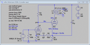
I attached a slightly simplified (no grid stoppers) L-W schematic using only 2 stages. It works in simulation, and probably also should in practice. However, I'm not 100% sure about startup and power down behaviour, so beware. Also, the EC86 is pretty finnicky, i'm not sure about parameter variation or long term stability.
It illustrates nicely how the noise (actually, PSU hum! not component noise!) works, by injecting a 180° out of phase hum from the output cathode to the input stage, just the same fashion as some negative feedback. The result is (almost) zero differential hum across the OPT primary, and hence on the speaker.
It should be clear that any phase shifts between output and input stage act against a perfect cancellation, hence better reduce the number of caps in the audio part of the circuit where possible. (Phase shifts are mainly introduced by caps!) We do require the cap between the cathodes because of voltage differential, and no audio signal passes thru it, so it's probably acceptable, but try and stay away from any further caps.
About your PSU ideas, they become largely irrelevant in the L-W circuit since almost no variable load is put on the PSU. The ultrapath cap forms a closed AC current loop together with the output tube and OPT. Yes, the current draw from the PSU will become nearly constant, the only variation caused by variations in the first stage current draw. Yes, this means that things like PSU sag or impedance will become virtually irrelevant anyways.
I would like to hear from any experiemnents you would carry out on any of your (test) amps in that spirit, since I appreciate your independent spirit and voice in the diy community.
BR
GB
Attachments
Member
Joined 2009
Paid Member
About your PSU ideas, they become largely irrelevant in the L-W circuit since almost no variable load is put on the PSU. The ultrapath cap forms a closed AC current loop together with the output tube and OPT. Yes, the current draw from the PSU will become nearly constant...
I tend to think this is semantics. In a non L-W topology there is still a final capacitor from B+ to ground and from the output tube cathode to ground, forming a loop that connects B+ to the cathode. Ground is just a construct, providing significant current doesn't flow from the ground to some point outside of the amplifier we can remove the ground symbol from the circuit. So whatever care is needed to make a good PSU, it applies in both cases but perhaps with different priorities (although they are not obvious to me right now).
Can you post the .asc file for your simulation (and associated library files) - it looks like a really useful way to see how it all works ? 🙂
Hi Jeff,
I attached a slightly simplified (no grid stoppers) L-W schematic using only 2 stages. It works in simulation, and probably also should in practice. However, I'm not 100% sure about startup and power down behaviour, so beware. Also, the EC86 is pretty finnicky, i'm not sure about parameter variation or long term stability.
It illustrates nicely how the noise (actually, PSU hum! not component noise!) works, by injecting a 180° out of phase hum from the output cathode to the input stage, just the same fashion as some negative feedback. The result is (almost) zero differential hum across the OPT primary, and hence on the speaker.
It should be clear that any phase shifts between output and input stage act against a perfect cancellation, hence better reduce the number of caps in the audio part of the circuit where possible. (Phase shifts are mainly introduced by caps!) We do require the cap between the cathodes because of voltage differential, and no audio signal passes thru it, so it's probably acceptable, but try and stay away from any further caps.
About your PSU ideas, they become largely irrelevant in the L-W circuit since almost no variable load is put on the PSU. The ultrapath cap forms a closed AC current loop together with the output tube and OPT. Yes, the current draw from the PSU will become nearly constant, the only variation caused by variations in the first stage current draw. Yes, this means that things like PSU sag or impedance will become virtually irrelevant anyways.
I would like to hear from any experiemnents you would carry out on any of your (test) amps in that spirit, since I appreciate your independent spirit and voice in the diy community.
BR
GB
Nice design. Plenty of current to drive the output grid. The "triode factor" for the input tube is a little low (about 3.2). If you don't mind a tiny bit of sand, you could reduce the cathode resistor by putting a schottky diode in series with it.
Sheldon
Last edited:
Maybe try running at about 3mA - 100k for R3, and 370 ohms on R2.
A rough calculations using the Philips specs sheet, suggests this will get you a "triode amp characteristic factor" of 6.8 (which of course is nicely over 4).
Ra/(mu*Rk+Ri)
Where Ra=100'000, mu= 15, Rk=370, and Ri=9'000
of course these values from the specs sheet are average, and were measured at with Va= 175V (not 96V).
The only think I don't inherently like is is the operating point of the EC86. Plate resistance and mu is much more stable over 10mA.
- Status
- Not open for further replies.
- Home
- Amplifiers
- Tubes / Valves
- 3 direct coupled 2A3 amps