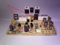
I test al transistors, they all seem ok, the amp worked for a few minutes then it died, i'll post some measurements tonight.
You must describe problem (oscilations, overheating...) just died can't help.
Are these tranzistors in wrong position or they are different parts?I test al transistors, they all seem ok, the amp worked for a few minutes then it died, i'll post some measurements tonight.
Attachments
Last edited:
Please, is there any PCB design other than Juan Vargas' for AX-20P?
I'd like to build this amp, and some inspection before building is always welcome.
Also impressions and hints would be nice.
Thank you all.
I'd like to build this amp, and some inspection before building is always welcome.
Also impressions and hints would be nice.
Thank you all.
The amp doesn't oscilate but I have 28vcc on out on both chanels, some tranzistor is malfunctioning, i measured all of them, they seem ok. I'll be back with some mesurements when I get home.
I've done some measurements on final transistors:
The psu in +/-30v, and on the output is 28vcc
2sa1943
GND-B-29.6v , B-E -0.02
GND-C-30 , B-C- 0.04
GND-E-29.5 , E-C-0.03
2SC5200
GND-B-29.4 , B-E 0.02
GND-C-28.9 , B-C 0.02
GND-E28.9 , E-C 0.02
The psu in +/-30v, and on the output is 28vcc
2sa1943
GND-B-29.6v , B-E -0.02
GND-C-30 , B-C- 0.04
GND-E-29.5 , E-C-0.03
2SC5200
GND-B-29.4 , B-E 0.02
GND-C-28.9 , B-C 0.02
GND-E28.9 , E-C 0.02
Last edited:
I've done some measurements on final transistors:
The psu in +/-30v, and on the output is 28vcc
2sa1943
GND-B-29.6v , B-E -0.02
GND-C-30 , B-C- 0.04
GND-E-29.5 , E-C-0.03
2SC5200
GND-B-29.4 , B-E 0.02
GND-C-28.9 , B-C 0.02
GND-E28.9 , E-C 0.02
Measure voltage on input and VAS transistors... check diode polarity there is mistake in first post.
Attachments
I've done some measurements on final transistors:
The psu in +/-30v, and on the output is 28vcc
2sa1943
GND-B-29.6v , B-E -0.02
GND-C-30 , B-C- 0.04
GND-E-29.5 , E-C-0.03
2SC5200
GND-B-29.4 , B-E 0.02
GND-C-28.9 , B-C 0.02
GND-E28.9 , E-C 0.02
Voltage reading taken incorrectly or written incorrectly.
2SA1943 collector should be negative -30v and 2SC5200 collector +30v from GND.
what psu you are using smps or transformer with bridge and filter caps.
Regards
Sonal
Last edited:
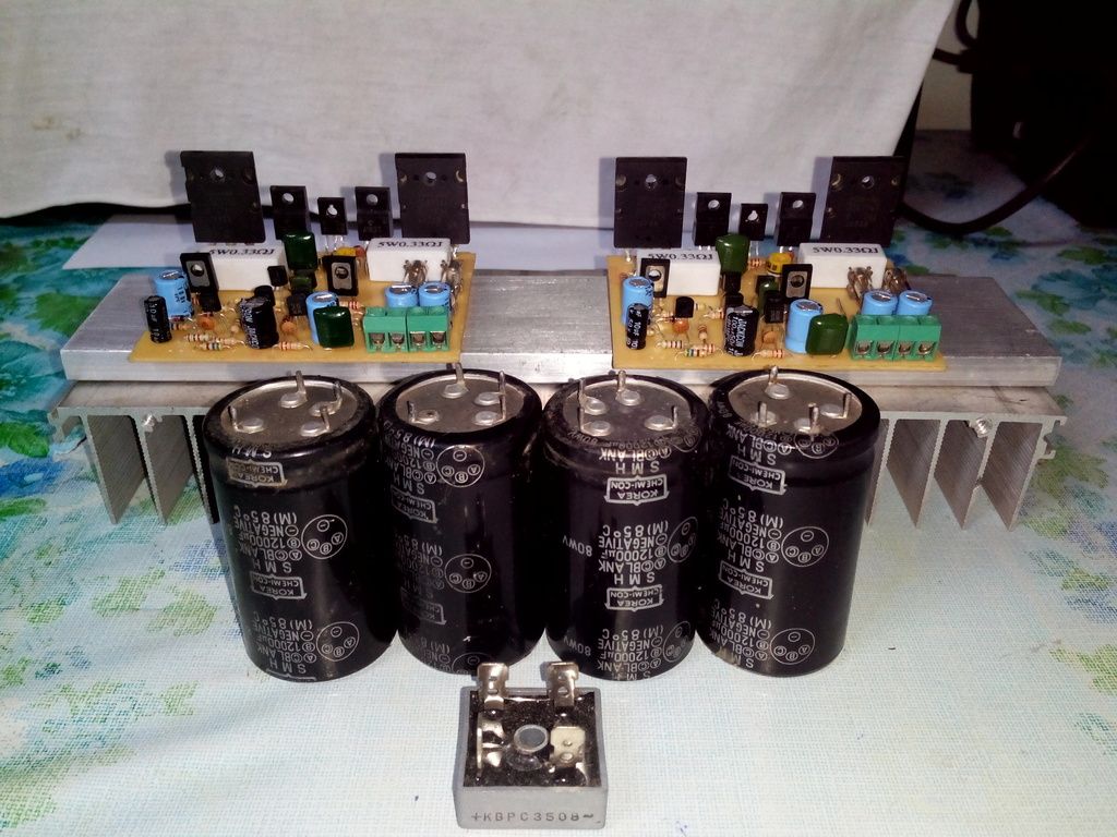
They might be written incorectly, i'll be back with some measurements tomorrow. This problem is at one chanel the other one seems to work post #4547. My PSU is +/-30VCC
Last edited:
Chanel one works, I replaced the fuses with 10R resistance and set to 115mv voltage drop., with input shorted I have 12mv on output.. I even made a sound test on a small speaker before I destroied it.
Last edited:

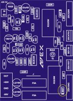
Size : 72mm x 61,5mm
Using 1/4w resistor
Some contribution to APEX amp Series
Regards
Nice work,
Regards
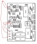
What pcb version you prefer for this AX-14?Nice work,
Regards
What pcb version you prefer for this AX-14?
PCB from post #1
Yes i see that is a beautiful pcb, but drawing a pcb isn't an easy way.Apex know this.This just redesign, just move fuse on a side.
Regards
Most of good amplifiers are drawing haven fuses close way each other,i believe that isn't without any reason.This way (+,-,gnd traces close each other)minimize the EMI.
Last edited:
Yes i see that is a beautiful pcb, but drawing a pcb isn't an easy way.Apex know this.
Most of good amplifiers are drawing haven fuses close way each other,i believe that isn't without any reason.This way (+,-,gnd traces close each other)minimize the EMI.
Yes like SR800 pcb
SR800???
Where is this 😉
In thread: http://www.diyaudio.com/forums/solid-state/173462-studio-reference-amplifier-112.html
- Home
- Amplifiers
- Solid State
- 100W Ultimate Fidelity Amplifier