I built a quick test box for one of my ACI subs to make sure the dimensions will work. It worked excellent in a 4 foot ported box until one of the glue joints broke and the box started rattling. I can definitely run more power. The amp was topping out around 200 watts with a 34VAC transformer. I can design the heat sink now.
Now you are blowing boxes apart with my amps , huh ? 😀
Not an OEM .... I foresee my speaker as the "weak link" in this
project , as well. This is the case on my main amp , never above
2/3 power - or she blows !
OS
Not an OEM .... I foresee my speaker as the "weak link" in this
project , as well. This is the case on my main amp , never above
2/3 power - or she blows !
OS
I'll have to poke around the speaker forums and see what people are building sub boxes out of these days. MDF doesn't seem to have much glue in it any more. I just built the test box out of cheap plywood without much bracing. I could feel the sides swelling.
Do you plan to mount your crossover vertically or horizontally? I'm going to get some decals printed to label the pots.
Do you plan to mount your crossover vertically or horizontally? I'm going to get some decals printed to label the pots.
Vertical. The side that does not have the amp's extrusion is 5" X 12". I
should have plenty of room for the +/- 12V ps's , protection , and EQ.
How big are the potentiometer holes ??
All my big heavy stuff is in my box. My box is glued, screwed , and
rabbited - never will it loosen 🙂 .
OS
The pot shafts are 7mm. The input is 11mm. It's been so long I can't remember what all I'm sending for aluminum. Am I sending a plate to mount the crossover in? If so I can pre-drill all the holes. It's pretty tight.
The pot shafts are 7mm. The input is 11mm. It's been so long I can't remember what all I'm sending for aluminum. Am I sending a plate to mount the crossover in? If so I can pre-drill all the holes. It's pretty tight.
Don't send yet , I have the sub out on the deck (wife kicked it out 🙁 ).
I have all the pcb's mounted , so I know what leftover space there is.
I'll have to draw some precision layouts.
Actually , I intend to put two small hinges on the amp extrusion and two more
on the control side.
I'll be able to swing the two sides out for tinkering
and/or "show and tell" . Fancy 😀 .
OS
I think I'm going to put all the supplies in the bottom of my sub box. I'm going to mount the amp with the input end up and the crossover right beside it to keep it away from the noise. The only downside is all the heat up there.
Your wife's had enough of your sub?
Your wife's had enough of your sub?
I think I'm going to put all the supplies in the bottom of my sub box. I'm going to mount the amp with the input end up and the crossover right beside it to keep it away from the noise. The only downside is all the heat up there.
Your wife's had enough of your sub?
"All the heat up there" ? You are not mounting the amp on the outside ?
All my amp will be outside the plate sitting 2.5" on top of those "C"
channels. It will stick out about 4" from the back , but be nicely
cooled by natural convection. Even the drivers will have airflow with
the perforated material I'll put on the top/bottom of the "C's".
Only the toroids , relays , bridges , and main capacitor bank will
be enclosed. All the real electronics will be in the open air.
I looked at a lot of real expensive subs - ALL have the electronics
IN the box. They may be a little better at wall placement , but
none will run as cool as mine (100F tennessee deck parties 😀)
OS
I'm going to try putting them inside the box. I'd like to put the subs as close to the wall as I can.
I switched amplifiers on the sub. Up around 250W I'm getting a rattling noise out of it around 40hz. Not sure if it's the driver reaching xmax or my crappy sub box self destructing. The box it traveling around the floor quite a bit and junk is falling all over my office so I think I'll design the amp for that output.
I'm not sure what to think of the crossover yet. I'm having a hard time getting the phasing to match the high pass speakers but this is through crappy computer speakers. I guess the only way to really evaluate it is to assemble a proper sub box and amp, then take it home and try it out with the rest of my theater system.
I'm not sure what to think of the crossover yet. I'm having a hard time getting the phasing to match the high pass speakers but this is through crappy computer speakers. I guess the only way to really evaluate it is to assemble a proper sub box and amp, then take it home and try it out with the rest of my theater system.
I switched amplifiers on the sub. Up around 250W I'm getting a rattling noise out of it around 40hz. Not sure if it's the driver reaching xmax or my crappy sub box self destructing. The box it traveling around the floor quite a bit and junk is falling all over my office so I think I'll design the amp for that output.
I'm not sure what to think of the crossover yet. I'm having a hard time getting the phasing to match the high pass speakers but this is through crappy computer speakers. I guess the only way to really evaluate it is to assemble a proper sub box and amp, then take it home and try it out with the rest of my theater system.
You really can't assess the project while running junk.
I'm not sure of the variable phase , but worse case we could make it
0/180 degree switchable. A variable phase will always have phase shift
according to frequency. Nothing is totally perfect in audio.
OS
You really can't assess the project while running junk.
I'm not sure of the variable phase , but worse case we could make it
0/180 degree switchable. A variable phase will always have phase shift
according to frequency. Nothing is totally perfect in audio.
OS
I'll get some lumber this week and build a proper enclosure for my sub. It's hard to assess a speaker when the whole room is rattling. My theater is a much better room to test in.
Should I be using some high end op amp in the crossover? I've got NE5532P in it now.
TL072 or OPA2134 would be a much better choice.
5532 is much lower input Z than the two jfet IC's.
OS
Hi Ostripper,
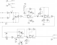
I am planning to make sub xover based on lars clausen design. However I am stuck in the values passives and connections of the schematic. attached is my attempt of the schematic. I know its pathetic but still in learning phase. can u have a look and suggest changes if possible?
reg
prasi
I am planning to make sub xover based on lars clausen design. However I am stuck in the values passives and connections of the schematic. attached is my attempt of the schematic. I know its pathetic but still in learning phase. can u have a look and suggest changes if possible?
reg
prasi
Attachments
Hi Ostripper,
I am planning to make sub xover based on lars clausen design. However I am stuck in the values passives and connections of the schematic. attached is my attempt of the schematic. I know its pathetic but still in learning phase. can u have a look and suggest changes if possible?
reg
prasi
Make it bigger/darker - can barely see it.
From what I can see , 12/oct very simple filters.
Our posted one is way better.
OS
Make it bigger/darker - can barely see it.
From what I can see , 12/oct very simple filters.
Our posted one is way better.
OS
Hi
here is the higher res image in monochrome. Hope its readable. (Hint. click on the four arrows at the lower left corner and it will open in biggger size. ). Also attaching the eagleschematic , if you use eagle..
also can u give the link to your posted filter?
reg
prasi
Attachments
Hi
here is the higher res image in monochrome. Hope its readable. (Hint. click on the four arrows at the lower left corner and it will open in biggger size. ). Also attaching the eagleschematic , if you use eagle..
also can u give the link to your posted filter?
reg
prasi
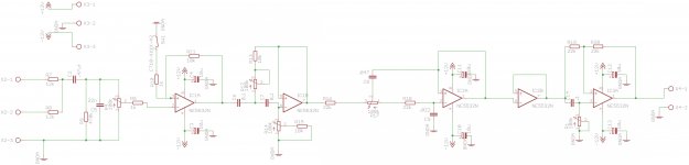
Yours has -
IC1a - input sum/X10 amp
IC1b - rumble HP 2nd order
IC2a - LP 2nd order (X-over freq)
IC2b - phase and output buffer.
This is a cheap car audio filter.
1st post of this thread is a better one
with 24/db octave LP.
U3.1 variable resistor from + input to ground was omitted.
Yours would work ,it would not have as sharp a LP cutoff .
Might hear a little midbass on your sub.
OS
- Status
- Not open for further replies.
- Home
- Amplifiers
- Solid State
- Subwoofer Class AB plate amp