An EF3 without local decoupling will oscillate for sure. They usually need a special rail decoupling scheme just to prevent it.
Meanwhile, tried to paste it onto a favorite chip amplifier, and mostly failed. . .
In order to put this input onto a properly AC coupled amplifier, you'd have to Cause the in+ coupler and in- coupler to require the exact same size (and model) of well matched capacitor. And, I really couldn't do that with a prefab amp--it would be a very special custom design indeed that could get away with that one.
But, here's what I tried with an old, old favorite.
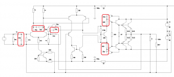
Attached is a mostly ineffective (maybe slightly effective!) attempt at translating that idea right onto the LM1875 Turbo II. That one is not newsworthy at all, mainly because it works without causing a lot of questions (and therefore not many posts). Anyhow, on the attempt, the proportions of both dividers is the same. The in- values are sky high so the amp doesn't explode at this voltage. The spread beyond 18% indicates the voltage is too high. Nevertheless, that thing is simple and the headroom adequate. It imitates the Honey Badger and other highly dynamic big amplifiers. However, just 22W in this case. The imitation succeeds up till about 15W. That's what she's for. I couldn't tell you if it does anything else.
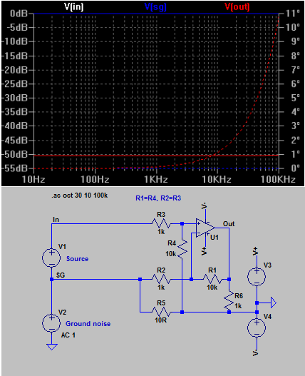
Mainly I added a 100n (guaranteed wrong value at the hopes of possibly being better than nothing bypass) to the groundlift. This bypass was to prevent simulating a very gone bad ancient dried up capacitor at the 100uF. So, that 100n is for preventing treble droop. That idea is generally applicable whenever you see a small signal groundlift resistor and wish it would be more practical to use. That bit was easily done! However, I suggest fine tuning the cap value more suitably.
I don't think that I did any other significant changes to the plan. Oh, except add AC coupling for more lifelike dynamics and intact speakers, both of which make an audio amp ever so much more practical and fun to use.
That is when the plan failed.
Notably, even if I pasted an exact copy of the inverting input coupling cap onto the positive input for coupler duties, the usage and frequencies used would be so very different that even 1% matched caps would only make matters worse and then with 38x gain applied, the noise filtering task would only be further hindered. When using the same caps (100u for both in+ and in- couplers), then the usage certainly wasn't going to match and in fact it would be a lot worse. SO, you know what? I drank two beers and just guessed the cap values. This plan is voltage reliant, and so similar RC frequencies was more important than matched caps. Even so, it is still far beyond the ~1% tolerance required, no matter what you do. That is because of gain. It is 38 times. Therefore, the matching gets 38 times worse. Ah. Nope.
I think it would work at 1x gain, but 38x foobars parts matching attempts, and on a fully ac coupled amp; well, that didn't go.
For sure, using a trimmer (a multi-turn cermet at variable resistor config) instead of the 2k7 would be a great idea. Mainly that's because if you've ever bought an audiophile grade resistor, you'll wish you'd have bought a cermet trimmer instead and put it right there. So that bit is fantastic. However, it won't help the common mode noise rejection significantly (but maybe slightly!). Mostly, that's a fail, except for being a wonderful place to stick a trimmer anyway, simply because every amp has a gain sweet spot and you can't dial it in if the dial isn't there.
This post was all about showing that it (post 101) needed to be a buffer, not an amp.
BV's plan (post 101) is brilliant, but it needs to be a buffer.
In regards to the attached amp schematic, I drank a little. But, that was necessary. Here's the proof.
In order to put this input onto a properly AC coupled amplifier, you'd have to Cause the in+ coupler and in- coupler to require the exact same size (and model) of well matched capacitor. And, I really couldn't do that with a prefab amp--it would be a very special custom design indeed that could get away with that one.
But, here's what I tried with an old, old favorite.
Attached is a mostly ineffective (maybe slightly effective!) attempt at translating that idea right onto the LM1875 Turbo II. That one is not newsworthy at all, mainly because it works without causing a lot of questions (and therefore not many posts). Anyhow, on the attempt, the proportions of both dividers is the same. The in- values are sky high so the amp doesn't explode at this voltage. The spread beyond 18% indicates the voltage is too high. Nevertheless, that thing is simple and the headroom adequate. It imitates the Honey Badger and other highly dynamic big amplifiers. However, just 22W in this case. The imitation succeeds up till about 15W. That's what she's for. I couldn't tell you if it does anything else.
Mainly I added a 100n (guaranteed wrong value at the hopes of possibly being better than nothing bypass) to the groundlift. This bypass was to prevent simulating a very gone bad ancient dried up capacitor at the 100uF. So, that 100n is for preventing treble droop. That idea is generally applicable whenever you see a small signal groundlift resistor and wish it would be more practical to use. That bit was easily done! However, I suggest fine tuning the cap value more suitably.
I don't think that I did any other significant changes to the plan. Oh, except add AC coupling for more lifelike dynamics and intact speakers, both of which make an audio amp ever so much more practical and fun to use.
That is when the plan failed.
Notably, even if I pasted an exact copy of the inverting input coupling cap onto the positive input for coupler duties, the usage and frequencies used would be so very different that even 1% matched caps would only make matters worse and then with 38x gain applied, the noise filtering task would only be further hindered. When using the same caps (100u for both in+ and in- couplers), then the usage certainly wasn't going to match and in fact it would be a lot worse. SO, you know what? I drank two beers and just guessed the cap values. This plan is voltage reliant, and so similar RC frequencies was more important than matched caps. Even so, it is still far beyond the ~1% tolerance required, no matter what you do. That is because of gain. It is 38 times. Therefore, the matching gets 38 times worse. Ah. Nope.
I think it would work at 1x gain, but 38x foobars parts matching attempts, and on a fully ac coupled amp; well, that didn't go.
For sure, using a trimmer (a multi-turn cermet at variable resistor config) instead of the 2k7 would be a great idea. Mainly that's because if you've ever bought an audiophile grade resistor, you'll wish you'd have bought a cermet trimmer instead and put it right there. So that bit is fantastic. However, it won't help the common mode noise rejection significantly (but maybe slightly!). Mostly, that's a fail, except for being a wonderful place to stick a trimmer anyway, simply because every amp has a gain sweet spot and you can't dial it in if the dial isn't there.
This post was all about showing that it (post 101) needed to be a buffer, not an amp.
BV's plan (post 101) is brilliant, but it needs to be a buffer.
In regards to the attached amp schematic, I drank a little. But, that was necessary. Here's the proof.
Attachments
Last edited:
Try it this way.
How will you stop ground loop currents flowing from AC1 through to to amolifier star ground with this scheme?
An EF3 without local decoupling will oscillate for sure. They usually need a special rail decoupling scheme just to prevent it.
EF3 for sure, but an EF2 using modern 30 MHz Bips can also be made to oscillate readily without basics like a Zobel, localized rail decoupling and base stoppers. I dont know what Cortez is using, but if its high fT bips then there's every reason to believe there may be an OPS instability issue. If just moving your hand around an amp, touching metal parts etc causes distinct changes in the sound of the hum or noise at the output, I would strongly suspect this.
How will you stop ground loop currents flowing from AC1 through to to amplifier star ground with this scheme?
R5 reduces the ground loop current in the same way it would do so if the resistor was places in the audio return. The difference is that the voltage that is present over the resistor is now only partly seen by the op amp's negative input instead of almost fully over the positive input.
What should be considered is what will happen if the resistor fails causing a break in the feedback loop.
For sure differential amp with unity gain (balanced input) is the best solution. But even 10 to 15 dB suppression is better than 0dB or positive gain for hum.needed to be a buffer, not an amp.
Use for an amp balanced input, connect unbalanced source differentially (3 wires with balanced impedance - resitor in ground sensing input, the same as is source output impedance), and you can get even 80-100dB supression for mains frequency.
Here are always ground currents, it is not possible to eliminate them fully (PSU parasitic capacity if are two or more components connected together). What we can , is to keep this influence of those currents outside signal loop or compensate their influence.How will you stop ground loop currents flowing from AC1 through to to amplifier star ground with this scheme?
For this reasons bypass this resistor with two antiparalell connected diodes.What should be considered is what will happen if the resistor fails causing a break in the feedback loop.
Answers:
And a request: could someone please post a screenshot from a scope about a completely
quite amp at 5mV/DIV with different base times to show me a perfect reference?
Thanks in advane!
I dont have a picture of my results now but it was about a 10-20mV "band" at 0.2ms/DIV and some sinus like waveform at 0.2us/DIV.
Is is just a normal HF noise (as I assumed... 🙂) or already a small oscillation that causes this high capacitive sensitivity..?
- Bonsai: yes, I am using (very) fast devices with 200-300MHz Ft (30MHz @ the very end).
- Keantoke: I attached the schematic so you can see the HF parts as well.
- Stability: when I had the scope of course I made it stable (in my understanding...) even to high and capacitive load.
I saw already on the scope that its a bit noisy but there was no oscillation even in peace and under heavy load.
Or if it looks that it is pretty sensitive to all capacitive garbage does this mean its still instable despite it is not oscillating? - Ostriper: What advise do you mean? I only skipped the LTP degeneration (which you suggested
agains my square wave overshoot issues) but at the end I managed to solve it in an other way. - Decoupling: I tried them of course during prototyping but it didnt helped then.
(But I'll try it again when I have my scope, if you all are recommending it so strongly... 🙂) - By the way I got the idea that the sensitivity of that OPS driver wires could be caused rather on the other (IPS) side due to the 10p HF FB cap?
And a request: could someone please post a screenshot from a scope about a completely
quite amp at 5mV/DIV with different base times to show me a perfect reference?
Thanks in advane!
I dont have a picture of my results now but it was about a 10-20mV "band" at 0.2ms/DIV and some sinus like waveform at 0.2us/DIV.
Is is just a normal HF noise (as I assumed... 🙂) or already a small oscillation that causes this high capacitive sensitivity..?
Attachments
Last edited:
That looks good.Andrew I draw a new schematic just for the essential wires.
What kind of error do you see on this? I think its perfect...! 😉
Sorry I forgot to tag the thing on the top right: it's the loudspeaker... 😀
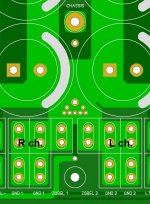
You have close coupled pairs for the signals.
Close coupled triplet for the power.
@Bonsai:
Thanks to your documents, i was learned many thing from your page.
I'm doing layout a new PSU, can i separate GND for each channel? Like pic, to get lowest crosstalk.
Thanks to your documents, i was learned many thing from your page.
I'm doing layout a new PSU, can i separate GND for each channel? Like pic, to get lowest crosstalk.
Attachments
Last edited:
Thanks for Sy to cut off the HF part and place it here:
http://www.diyaudio.com/forums/solid-state/270230-heatsink-vs-os-stability-2.html#post4272131
The HF part will continue there... and of course I'll report it back here it is related to my hum issues.
http://www.diyaudio.com/forums/solid-state/270230-heatsink-vs-os-stability-2.html#post4272131
The HF part will continue there... and of course I'll report it back here it is related to my hum issues.
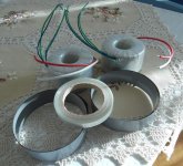
My new trafos just arrived yesterday (I said them a bit late the mods so
only the belly band is on and the screen not, so next time...) but I also
asked for the matarial for a "post factum belly band" for my old trafos so
I can try soon their magnetic shielding effect with my EMF detector...
(Yes I know, nice cloth... 🙂)
only the belly band is on and the screen not, so next time...) but I also
asked for the matarial for a "post factum belly band" for my old trafos so
I can try soon their magnetic shielding effect with my EMF detector...
(Yes I know, nice cloth... 🙂)
Attachments
My new trafos just arrived yesterday (I said them a bit late the mods so
only the belly band is on and the screen not, so next time...) but I also
asked for the matarial for a "post factum belly band" for my old trafos so
I can try soon their magnetic shielding effect with my EMF detector...
(Yes I know, nice cloth... 🙂)
Wrap toroid with thin layer of sheet neoprene , wrap band around that -
wrap the tape around those first two layers.
Done !
OS
I wonder what effect different band metals have on leakage inductance and rectifier damping? After all the band is interacting with the leakage inductance directly.
Good news: my HUM with a free input has 100%-ly gone.........!!! 🙂
Cause: it seems the IPS-OPS driver wires took up the EMF probably due to the (coneventional) high impedance FB resistors. (1k/51k)
I changed them to lower values (based on this article by Esperado) and now it is completely hum free.
(Although the 1m long sec wires are still up and running...)
Now its not sensitive to any touch, the microphony of that wire has gone as well, neither I have to ground the heatsinks, etc...
However (how typical life is...) now when I connect my source a ground loop hum appears... 😀
So maybe now I can get back to the GND lifter resistor again...
(I tried earth related things like disconnect it from SGND, connect it via 0R, 10R but still there...)
Belly band: I also tested my "post factum" material with the DIY EMF sensor and it really does a great job..!!
Of course it doesn't eliminate the EMF 100%-ly but but about 75% (by ear....)
Last edited:
Does the belly band act as a shorted turn like it does with a Faraday ring on a magnetic circuit, do you ground the band?
No I did not ground it, even without a loop it is working if I put it between the trafo & the sensor.
A toroid has two loop planes. One is the loops through the toroid, the other is a loop parallel to the toroid, which is responsible for the stray field. This loop is shorted by the band. Magnetic bands would be more lossy, but I think maybe the idea here is to provide magnetic shielding for the first plane as well.
Cortez:
Changing the feedback resistors will also change the stability compensation. So it is possible you have stopped oscillation mostly or you have simply made it oscillate 100% of the time at a lower level so that transistors don't saturate leading to hum, and you don't hear pops every time it comes in or out of oscillation.
In any case, it is easily possible that it is not the global feedback loop that is oscillating, but a local parasitic loop in the output stage. If so then the feedback compensation can at best not aggravate the parasitics in the output stage.
Of course, many builders seem to be satisfied with this, and I can't blame them if they don't have a scope. This is something that can only be done by someone with a scope, which is either the original designer or the builder with guidance. Furthermore, the long wires to the output stage could really be messing with stability, causing coupling scenarios that were not present in the original design.
It looks like now everything is okay, no oscillation, no hum (just a very very very tiny but maybe rather the fridge in the kitchen... 🙂).
The ground loop was caused by the 3 earthed devices: amp, PC, scope together.
For a test: If I plugged the scope to an unearthed outlet the hum disappeared immediately...
The ground loop was caused by the 3 earthed devices: amp, PC, scope together.
For a test: If I plugged the scope to an unearthed outlet the hum disappeared immediately...
- Status
- Not open for further replies.
- Home
- Amplifiers
- Solid State
- Ultimate Hum Terminator Thread