No C @ OPS but of course I had a scope during the building phase and I made it stable with this setup even to capacitive load.No output stage decoupling? I am also worried that you might have HF oscillation.
Stability: yeah, I had the same experience when there was some oscillation and the hum appeared.
Now I dont know whether this is the case so I'll get a scope again but I cant hear a whistle or anything
like that just the hum and te conventional white noise.
But when I had the scope I saw that during switching off the amp it did oscillate but I guess that's just some temporary thing.
Although at swithing on there are some settling phase about a few seconds and during that the hum is louder as well and
then it settles to a low level (but clearly hearable with ears on the speaker).
It did not change the hum level. Without the scope I just adjusted them slightly. Did you mean to set Iq = 0..?Try reducing the OPS bias and see if that changes the hum.
I dont think so: as I said loading the PS with a dummy load cause a hum but a bit different kind andMy guess would also be that there is an excessive current demand causing excessive voltage ripple.
not so loud though I used 8R for the 56V Vs (7A > I cap charging * X...)
And here are the results about trying different signal GND routes to PS GND:
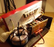
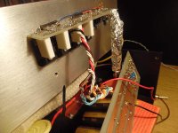
Amp disassemled as you can see @ attachment.
- trying a 1k pot instead of 10R resistor
result: clearly the hum increases but another kind then the basic one
> 100R another type came up much like a conventional ground loop with that strong "metal buzzing"...
the lowest hum was at 0R position - wiring it directly to the rectifiers
result: as expected highher hum appeared - wiring it to somewhere at the 1st filter caps
result: already much less noise - wiring it to the 2nd filter cap
result: almost nothing - wiring it to the end:
result: the less noise - wiring it around the IPS PS GND:
result: the same as at the end of the "T"
Other interesting experience: when I put my palm near the trafo (around like a belly band),
the hum first decreases and to a tight grab it changes to another kind of sound (deeper hum) about
the same intensity. And because I am not build of metal and the trafo is isolated galvanicaly this
should be a capacitve change..? Am I right?
Next things to try Watson...? 🙂
Attachments
Last edited:
Hehe, 21st century... maybe it helps! I attached 2 sound files (VLC can play them)
but be carefull there is some pitch noise in the first one around 40sec!!!
The first one is a complete switch on/off process as you can hear the swith clicking as well:
Is the hum a bit varying with the time slowly am I right?
Can be a waving DC level the cause..?!
The 2nd on is with a turned on amp and touching the trafo with my hand 2 or 3 times.
I think its clear when because of greater hum.
Attachments
You had obviously build an oscillator.I attached 2 sound files.
Try it this way.
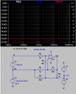
Okay, I've thought about this more. This a nice solution when the conditions allow. However there are some problems:
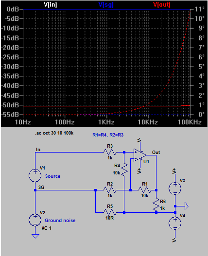
1: The source resistance must be near zero or else the input and feedback dividers are not matched, resulting in little ground noise rejection. So you would have to use a buffer after your pot.
2: The ground noise rejection is only as good as the input and feedback divider matching. With 1% resistors at worst case you get 2% mismatch which is -26db. The second limitation is input stage CMRR. So SE designs might have trouble too.
The common-mode choke input trick I shared however gets up to 70db ground noise rejection depending on the CMC you use, and the amp input CMRR doesn't matter because the ground noise doesn't reach the input stage. All this and it only takes a CMC and a resistor.
Oh, it was made for me? Thx BV! Sorry I thought its for the other discussion with Bonsai about the ground lifter.THAT's how it should be done! Thanks.
As you can see I already tried to separate the 2 GNDs but it only increased the hum.
Or this way it is completely different and worth a try..? It would be a bit greater modification due to the already existing PCB.
What did you hear? 🙂You had obviously build an oscillator.
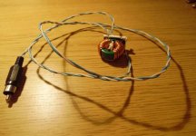
By the way I also built my EMF detector as attached. It really works great.
And there was 1 very strange phenomena which I dont understand right now:
around the 2 thick wires which connects the 2 heatsinks the noise was surprisingly big.
Not so much as the trafo of course but I thought there will be ~ 0... 😕
Other thing: after a while a the hum increases and when I touch the trafo and the secs this increment goes away...
What this can be..?! Some capacitive charging?!
Attachments
Last edited:
Cortez, it wasn't a suggestion for you but it would be a great mod for your amp if it weren't for the problems I pointed out later. And in any case it seems that ground noise isn't your problem.
Also I like your idea of using a toroidal CMC as a magnetic probe. It should be best to put the coils in series, zigzag style.
Also I like your idea of using a toroidal CMC as a magnetic probe. It should be best to put the coils in series, zigzag style.
Last edited:
You are right, its much more sensitive now..! 😉Also I like your idea of using a toroidal CMC as a magnetic probe. It should be best to put the coils in series, zigzag style.
Attachments
The speaker return wire is taken to the wrong point.................
See the attachment, thats how I wired my PS to OPS @ Speaker.
The Return wire must follow the Flow wire all along the Flow wire route.
Now show the rest of your grounding wires.
You said earlier that Signal Ground to Power Ground might benefit by changing the resistance of the wire connection. This implies that speaker loop interference could be injected into the signal return route and then becomes amplified.
Last edited:
Choke: It's a "Falco T10051" CMC.
I tried it both way and this way was the loudest.
Hum: Good news...! I think I am on track now...! 🙂
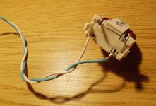
I "shielded" the driver twisted pair wires (going from IPS to OPS which is a very sensitive EF3 OS)
and now the hum is much lower...! Still not 0 but much better now.
This piece of wire (which is now twice as long because of testing situation) looks very very sensitive.
It is microphonic as well: every touch induces a tick @ output and when I flick it even with a piece of paper it ticks...
The shield is just a 3rd piece of wire around it. I tried to connect it both to GND and to heatsink but leaving it free is just as good.
The old experiences (AC plug polarity and touching secs, trafo, heatsink) are still there but with a less influence.
If this is really the weak point how should I shield it perfectly?
I dont have any pro shielded cable. Alu foil should do it temporary for testing..?
And does this mean that it is very sensitive to "capacitive radiation"..?
By the way its still strange but on switch on the hum changes from low level to loud and then settled the the minimum...
What this means..?!
I tried it both way and this way was the loudest.
Hum: Good news...! I think I am on track now...! 🙂
I "shielded" the driver twisted pair wires (going from IPS to OPS which is a very sensitive EF3 OS)
and now the hum is much lower...! Still not 0 but much better now.
This piece of wire (which is now twice as long because of testing situation) looks very very sensitive.
It is microphonic as well: every touch induces a tick @ output and when I flick it even with a piece of paper it ticks...
The shield is just a 3rd piece of wire around it. I tried to connect it both to GND and to heatsink but leaving it free is just as good.
The old experiences (AC plug polarity and touching secs, trafo, heatsink) are still there but with a less influence.
If this is really the weak point how should I shield it perfectly?
I dont have any pro shielded cable. Alu foil should do it temporary for testing..?
And does this mean that it is very sensitive to "capacitive radiation"..?
By the way its still strange but on switch on the hum changes from low level to loud and then settled the the minimum...
What this means..?!
Last edited:
I dont get it, how do you mean? Where it should go and whats wrong with this layout? The current loops are minimized this way arent they?!The speaker return wire is taken to the wrong point.
The Return wire must follow the Flow wire all along the Flow wire route.
You can see every GND point and connection from the previous pictures.Now show the rest of your grounding wires.
You said earlier that Signal Ground to Power Ground might benefit by changing the resistance of the wire connection. This implies that speaker loop interference could be injected into the signal return route and then becomes amplified.
About SGND for me using a piece of wire is the best so far, 10R just increased the hum
(or to be precise: probably it brought in an extra ground loop like hum)...
Those parts should be 0.1% or better match.Try it this way.
Try it at 1x gain, aka a buffer.
That will make parts matching efforts work.
With that circuit it is not practical to put gain on differences because then the filter scheme effectiveness is reduced in direct proportion to the gain.
yeah, so, that should be a buffer.
And I was guessing, but I tried to make that work for an amp and couldn't, because gain.
Last edited:

Grrh, I dont get it... I took off this 3rd wire to try out a piece of alu
foil but now its the same and silent without the 3rd shielding wire...
Maybe its late now... I go and have a little break (and a Kitkat.. maybe...)
foil but now its the same and silent without the 3rd shielding wire...
Maybe its late now... I go and have a little break (and a Kitkat.. maybe...)
Those parts should be 0.1% or better match.
And your source impedance had better not be above 1 ohm, because then the input divider is not matched again. So if you use a pot you need a buffer between the pot and the input...
A schematic would really help here, because it seems obvious now the amp is oscillating. Essentially when you touch it or put aluminum somewhere you are modifying antennas and fields.
- Status
- Not open for further replies.
- Home
- Amplifiers
- Solid State
- Ultimate Hum Terminator Thread