Hi ROhin and others,
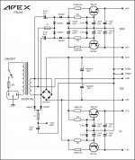
Based on the suggestions and inputs received and also some web browsing, I have put together a small PSU PCB which will be used to drive APEX mono LM3886 amp and APEX Sub Xover. attached as a pdf file.
pl review if you find time and point out gross mistakes and suggest any corrections/ modifications.
thanks all,
prasi
Attachments
don't try it..you cann't use one dc for preamp or crossover and amp. your 7815 will blow in first try.Hi ROhin and others,
Based on the suggestions and inputs received and also some web browsing, I have put together a small PSU PCB which will be used to drive APEX mono LM3886 amp and APEX Sub Xover. attached as a pdf file.
pl review if you find time and point out gross mistakes and suggest any corrections/ modifications.
thanks all,
prasi
don't try it..you cann't use one dc for preamp or crossover and amp. your 7815 will blow in first try.
Hi thanks for the reply , if thats the case, can I use some passives to drop the voltage to acceptable levels?
regards
prasi.
you are not getting point. you can make so much different voltage from one source this is not problem.this depend on application.here your application is amp and crossover.with this type of circuit you will get noise.you have two option use two trafoo for 7815 or use this apex circuit.
Dear Apex Sir,
thanks for the schematifc. I would think its a bit complicated for a beginner like me. But still I would try. Do you have pcb for the above schematic which I can simply use through ironing method to print PCB?
regards
Prasi
thanks for the schematifc. I would think its a bit complicated for a beginner like me. But still I would try. Do you have pcb for the above schematic which I can simply use through ironing method to print PCB?
regards
Prasi
Hi rohin,
Thanks for the reply. OK I get your point. I will try to use two seperate trafo o/p (24-0-24 VAC for amp and 12-0-12 VAC for X-over)
reg
prasi
Thanks for the reply. OK I get your point. I will try to use two seperate trafo o/p (24-0-24 VAC for amp and 12-0-12 VAC for X-over)
reg
prasi
no need to add two 2200uf only two is sufficient and 2 10000uf is enough.this x over bass response is good.hi rohin,
here is another version of pcb with separate inputs for amp and xover. pl suggest ur views.
reg
prasi
PS : I know not the art of PCB designing, so sorry if the pcb looks ugly!!!🙂🙂🙂
thanks a lot. So can I go ahead with printing of the PSU PCB? I already have the Xover PCB .
reg
prasi
reg
prasi
According to my schematic
So, if I were to use an xlr on one channel of my current schematic, Pin 1 would go to chassis/signal-GND, Pin 2 would go to signal-IN, and Pin 3 would also go to chassis/signal-GND. Would this be the proper layout to provide phantom power to the mic, or would I need to add any components to Pin 3 entering the preamp, and if so, where does it terminate within the preamp. Sorry for my crappy wording. This is what I have so far (If XLR is used):
Current (linked) schematic:
- Mic 1 > Preamp 1 > Chassis/GND [metal housing AND one pad connected to PCB ground plane]
- Mic 2 > Preamp 2 > PCB signal input pad > caps/resistors/opAmp/etc [9v powered] > Signal Output
- Mic 3 > *SEE Mic 1*
- Mic 1 > Preamp 1 > Chassis[metal housing]
- Mic 2 > Preamp 2 > PCB signal input pad > caps/resistors/opAmp/etc [9v powered] > Signal Output
- Mic 3 > Preamp 3 > SWITCH A > PCB ground plane
- > SWITCH B > ?(resistors and/or caps and/or battery +/-)>?(where to from here)[/INDENT]
why not.that all about fun.self made and fun.better than market not only cheap.thanks a lot. So can I go ahead with printing of the PSU PCB? I already have the Xover PCB .
reg
prasi
The correct connections for a phantom powered mic circuit are:
XLR
pin 1 : chassis & phantom supply common.
pin 2 : signal & through a resistor to phantom supply hot.
pin 3 : signal & through a resistor to phantom supply hot.
The resistors are 6800 Ohms
While the XLR connector is not part of the audio circuit common, the best place to connect the circuit common to the chassis is near the input chassis jacks.
Dear Mr. Apex,
What will happen if I connect LFE out on receiver to the left channel of the input of sub x-over? will it work? this has reference to your sub X-over circuit post earlier in the thread.
reg
prasi
What will happen if I connect LFE out on receiver to the left channel of the input of sub x-over? will it work? this has reference to your sub X-over circuit post earlier in the thread.
reg
prasi
Last edited:
Dear Mr. Apex,
What will happen if I connect LFE out on receiver to the left channel of the input of sub x-over? will it work? this has reference to your sub X-over circuit post earlier in the thread.
reg
prasi
X-over can use signal from speakers outputs or line record outputs and can work with only one channel on input.
Regards
As I said earlier, I am not good at PCB designing. If someone wishes to redesign the board so that it can be used by other diy audio members as a PSU for driving amplifier as well as tone controls/ sub x-over, I am ready to post eagle pcb here.
regards
prasi
regards
prasi
Stereo tone control with 2x10k
Dear mile sir....
I am planning to build your stereo tone control circuit with 10k pots. where should I connect the volume control pot? At the output of the circuit or at the input? Also what should be the value of the volume pot?
Dear mile sir....
I am planning to build your stereo tone control circuit with 10k pots. where should I connect the volume control pot? At the output of the circuit or at the input? Also what should be the value of the volume pot?
Use 10k pot at the output of the circuit.
- Home
- Live Sound
- PA Systems
- Mic, Line, EQ... Preamps