I find, much to my dismay, that usually someone has thought of my brilliant ideas before me 🙁
That said, some searching here reveals the Panpipe and similar horn or TL designs. Recently I've been bitten by the line array bug but have yet to build one. I have a history of tinkering with basic TL because they are so easy to make. My latest effort is the Polluto I and II which is just a 4" cardboard tube with a fullrange (4.5") glued on top. So the idea occurs: has the following ever been tried?
A line array of identical drivers (common) but each driver has its own TL tuned to a different frequency? The closest I found was the Panpipe. My idea would seem to avoid the issue of one driver with multiple loadings. Can one simply sum two or more (many more!) varying TL systems to get the common response?
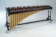
Since the name "Panpipe" is already taken, I propose the name "Marimba" for my idea. I have no graphic skills, but look at an image of Marimba and imagine the pipes underneath turned 90 degrees. I'd put longest pipe at floor and stack 'em up vertically.
Given my preferred "medium" (free 4" cardboard tube and coroplast) this would be perhaps much easier to build than to model on the PC 🙄
That said, some searching here reveals the Panpipe and similar horn or TL designs. Recently I've been bitten by the line array bug but have yet to build one. I have a history of tinkering with basic TL because they are so easy to make. My latest effort is the Polluto I and II which is just a 4" cardboard tube with a fullrange (4.5") glued on top. So the idea occurs: has the following ever been tried?
A line array of identical drivers (common) but each driver has its own TL tuned to a different frequency? The closest I found was the Panpipe. My idea would seem to avoid the issue of one driver with multiple loadings. Can one simply sum two or more (many more!) varying TL systems to get the common response?
Since the name "Panpipe" is already taken, I propose the name "Marimba" for my idea. I have no graphic skills, but look at an image of Marimba and imagine the pipes underneath turned 90 degrees. I'd put longest pipe at floor and stack 'em up vertically.
Given my preferred "medium" (free 4" cardboard tube and coroplast) this would be perhaps much easier to build than to model on the PC 🙄
Attachments
O/P, I'd assume this wouldn't bode well with line array action where the drivers are not working together unless this happens below the line frequency. Except of course that you want to run it floor to ceiling...
Why not randomise their positions similar to a diffuser?
Why not randomise their positions similar to a diffuser?
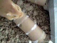
A gerbil's take on transmission lines...
Hmmm, making them more diffuse? I guess I could; however that would destroy any symmetry of a stereo pair.
Here are some "thought experiments" based on my wishful "knowledge of acoustics" 🙂
Imagine the Marimba Mark I to be a (small vertically) line array of 8 drivers per side, or even 9. Either would make wiring easy. If using 9, it would be electrically like a Bose 901 speaker.
Similar:
direct radiator to the front (duh, line array), but all drivers in the same vertical plane.
rear outputs are staggered but Marimba's wil be due to varying tube lengths: both will give the "reflections" off a rear wall but the Marimba will be mostly LF and also with varying phase as well as distances really mixing stuff up.
Different:
The Marimba will have more efficiency since it is making use of the back wave.
Instead of the 901's 19% forward, 89% backwards radiation that will perfectly recreate any concert hall in your tiny room 🙄 the Marimba will combine the "in your face" of a line array with a computational nightmare's worth of reflected signals off the back walls.
I can vaguely understand that even just considering the forward drivers, each driver may not be putting out the same signals, but wouldn't that only be true at resonances in a certain tube? Also if series/paralled, I understand even less clearly that drivers can interact. So? At least I can avoid that problem if I choose to wire up 18 channels of amplification...
The Polluto II's performance is quite acceptable... so the next question should be:
How do I figure the optimum length of each tube? I think the Panpipe builder chose 10% difference between tunings and the objective is to spread the resonances around an octave or so (around what? the Fs of the driver?)
The photo shows that the common gerbil has a far more practical attitude to "making sawdust" as well as use of cardboard tubes. The detritus would probably be good stuffing.
Attachments
Hi,
Your fundamental problem will be at what low frequency
each driver becomes unloaded (like vented boxes) and
a general lack of bass due to most of the TL's not
matching the parameters of the drivers properly.
So basically, not a good idea. Same goes for line arrays
in general, if you don't thoroughly understand them
they bite back, doing things you really don't want.
rgds, sreten.
If your considering some form of line array I'll point you towards what I consider a good starting point :
ZA5.5tt - MMTMM : Zaph|Audio - ZA5 Speaker Designs with ZA14W08 woofer and Vifa DQ25SC16-04 tweeter
Its not a proper line array, so avoids all their pitfalls, but has some good line like qualities.
rgds, sreten.
Last edited:
Thank you sreten, a known Bose-hater 😀
I did some more reading and the Marimba is, at minimum, a different animal than the Panpipe: instead of multiple columns dependent on one driver, won't my case, in which multiple columns are totally independent of each other, be different?
This doesn't make my idea any better just differenter 😛
Sreten posits something valid to my idea, though: I need to consider the LF rolloff of my TL(s): since the 901 depends upon huge bass boost, will this be workable with multiple TL's?
Hi,
No. TL's just like vented boxes unload the driver below resonance.
i.e. front and rear driver outputs cancel, roll off is 24dB/octave
and any bass boost will simply cause gross distortion.
The shorter the TL the worse it will be, nevermind as I've
already mentioned, the short TL's won't match the drivers.
For both TL's and vented, you need to keep the tuning low
for bass boost, and cut low bass below the tuning point.
Many simply get away with a low tuning point, assuming
most programme has little content below the tuning point.
rgds, sreten.
Another point of disagreement...I'm sure I've heard someone (Risch on his web site perhaps?) say that a TL rolls off gentler than a ported driver. Even if you are right, one thing I have in favor of my current project is this: the driver I use will be in something approaching an optimum sized box, er, tube for the given driver. In contrast, in the design of the Bose 901 they deliberately raised the system resonance up to 200 Hz (IIRCF) with the intention to boost with EQ below that frequency. So I am getting optimum output down to around my Fs which is around 106 Hz average.
Hi,
Eventual roll-off of vented and TL's is the same, rear cancels the front.
In both cases you can't boost below the tuning frequency, simply won't work.
The 901 has a high Fb for each driver in the box, don't think its as high
as 200Hz, I think its a little below 150Hz, and an isolated bass tuning
peak, about 40Hz, which determined how low you can boost the bass.
rgds, sreten.
Replacement Speaker Driver for Bose 901 4-1/2" 1 Ohm
A TL / Quarter Wave has stuffing which reduce the cone movement below tuning. Imp plot will show that.
Bjørn
Bjørn
Recent developments in TL design have shown recommended alignments produce a result closer to a closed box (Augspurger and others from around this time). When used below the critical room frequency it's debatable whether anything but a closed box response is necessary for getting the best out of a particular driver.Another point of disagreement...I'm sure I've heard someone (Risch on his web site perhaps?) say that a TL rolls off gentler than a ported driver.
Speaking off the top of my head, or more precisely out a body orifice that I cannot name 🙂
...Sreten sounds correct about the Bose 901 "box", but is this for the sealed (I, II) or ported (III onward)?
It's intereting that there is still lack of agreement on the aspects of a TL. Not that I know them all, far from it. I think Risch on one of his web pages notes this is due to the decades that were pre-King and Augsberger before formulae were devised, and some of the folk wisdom (some of it wrong?) lives on.
Perhaps the closed box is all that's needed (heck, even when I was young -- 1982, the stereo guides noted this is by far the simplest and least likely for things to go awry). Let's not get into whether I'm using "good drivers" (just on-hand ones) ... but I'd like to get the best out of one, or nine. And even if AllenB is right, and my measurements are too, then my 76 cm long 4" cardboard tube is a simpler enclosure than whatever the proper size sealed box is 🙂
Below tuning a tl acts like a leaky box. Impedence and excursion is reduced, but the later is not reduced as much as many think. Boosting below tuning just like with br types is an absolute no no. Distortion rises astronomically and excursion, while better damped still rises well above Xmax.
In my modeling and based from measurements you can achieve a result that is more like that of a sealed enclosure as far as group delay is concerned and extension of a br.
If possible a tl system design that includes tuning below 30Hz handles an A note (27.5Hz) without issue. For music (not ht) this is low enough to sound like bottomless bass and without exceeding Xmax. My latest will do this within a maximum of 12mm pk-pk, but once I hit 22Hz Xmax peaks at double it's maximum eg Xmech! Below tuning distortion rises exponentially. Playing music from vinyl or for HT use requires a subsonic filter and provides two functions. The first reason prevents driver damage while the second is to keep this non musical distortion in check.
Last edited:
I don´t expect infrasonics even from the Mythical Bose 901 drivers 😀
Facts and misgivings aside, my current experiment continues...latest idea I swiped from the Penthorn or Panpipe threads: let me spread the resonant peaks and nulls around an octave or so. Rather than make the smallest pipe one octave higher which would in theory fill in the null caused by the low pipe, also keeping in mind what Sreten says, why not instead do this....
Until proven otherwise my optimum length (a bit shorter actually, because stuffing makes it acoustically longer said a wise man) is 76 cm. I want to use the guts of a 901, so that´s 4 drivers lower and 4 higher. The lowest will be half octave below 76 cm and the high half above. My hypothesis for this is that 76 cm is close to the correct tuning for the CTS driver. So I am reasonably close to the optimum tuning and still have the chance to spread out the peaks and nulls.
If the project is a success, instead of a milquetoast name like Marimba I might call it the Bose MLRS because Wave Cannon was already taken
Attachments

Your biggest peaks and nulls will be from your coupling to room modes. Distributing your woofers in space is the best thing you are doing to reduce these peaks. Supplemental EQ can be made at any woofer or all together. This would be complicated if each has a different arbitrary rolloff.
Last edited:
You hit upon one of the 901´s features
in an ancient review of the 901 system, the reviewer says the multiple drivers excite many room modes and this contributes to the apparent bass depending upon accident of type of room.
Yes my system will have not just 9 drivers per side but 18 for twice the excitement, so to speak.
I am going to build one side or maybe even both, a few pipes at a time. Even the single pair of perhaps correctly tuned 76 cm. pipes sound pretty good with EQ. Using a RTA it is obvious that the 200 Hz is missing.
Next challenge is how to stack them up vertically.
Sreten: I note you are from Brighton. I've never been there, but per 70s rocker Queen, Brighton Rock. Brian May sure does have fun with his guitar on that song...
It has occurred to me that I have stumbled upon an idea so whacked that even my usual inspirations like Patrick Bateman or xrk971 haven't thought of a vertical array of line array transmission lines yet 🙂
Tuning the line(s): it is what it is. I don't think I have it tuned for much less than 106 Hz. I guess that bass boost below tuning is a no-no. I will still try of course
It can't sound any worse than Bose 901 speaker (ported) when fed a < 40 Hz signal (I don't think they're supposed to go below about that.) Sounds like a blacksmith's bellows on acid 🙂
I am considering different (cheap) ways that I might make the framework to support the 8 or 9 tubes. Even though each tube is sturdy, I don't want the bottom ones to support the weight of all the upper ones. So some kind of frame work...how to attach each tube? They probably should be isolated from each other.
Here are some easy ideas: (1) rubber pads attach them to support rails. There is no need for one tube to touch another. (2) oh screw it, why not just cement all the tubes to each other 🙂
Photos soon...
Hi,
IMHO your now chasing a not good idea you should give up on.
I dislike half baked line arrays with a passion, expensive in time,
money and effort, and hardly ever deliver anything worth the effort.
They are not something you can design on the back of an envelope
using vague ideas that they somehow will turnout to be fantastic.
Problems are legion, if you don't know them, its not a good idea
to hope for the best and ignore them, they will eventually bite.
Any experimenting requires far too much time, money and effort.
rgds, sreten.
I'd agree with you about the issues. I hardly have the right to talk about experimenting though as I've burned too many old speaker boxes (including TLs), and you know, disassembled old speakers for my aunt who likes to use the magnets as pin cusions in her sewing room.Problems are legion, if you don't know them, its not a good idea to hope for the best and ignore them,
Anyway, if you are expecting a collection of differently tuned TLs to do some averaging of their response, they ought to be all in the same point in space. You may still gain some benefit but it will be in the hands of the room and its modes. Peaks and dips may swap, or change level, and basically not couple between drivers as expected. Essentially it will come down to some randomness, although it could be predicted with some effort.
Which would leave you with some questionably tuned lines. These may even hinder attempts at minor corrective EQ.
Not saying it can't be done. I guess my opinion is that there would have to be some discernable benefit to the excercise. Still, this is DIY.
AllenB, you have given me another idea. I probably can't get all 9 TLS at one point in space, but as being built, they are modular and I can try different configurations . It's just that my original idea was a vertical line array. Other options might be:
Bunch multiple TLs so they are a square or circular source towards the listener. I have them marked with their tuning (length) so I can mix and match.
Easier to experiment than simulate? Yes, very much so in this case! Other than Hornresp, I lack the software or the knowledge to do more complex simulations. It took me months to get competent even to simulate a basic TL. Multiple TLs indpendently positionable in 3-D space? Good luck!
The results are very room-dependent. That's true of any speaker, especially for the unspeakable speaker that is the organ donor for this project !
Y'all may very well be right about my wasting time and effort. But materials and money -- almost none in this case. The drivers are free (already spares on hand). Unless from too much power, they are unlikely to die during the experimenting. Cabinet materials are mostly free save for a few board-feet of lumber. The "cabinets" are free scrounged tubes. The only consumables are wiring, solder, Gorilla Glue, and misc.
I am a skeptic. Allowing that those of you kind enough to critique my idea are knowledgeable, which I don't doubt, I still want to (dis-)prove for myself the merit, or lack thereof, in some of these ideas. Certainly a TL broadly speaking is a valid goal, perhaps not with my materials at this time
Having put this much time and effort into it, at the minimum I will do some sweeps of a single finished unit and post them for your amusement and my abusement 🙂
Last edited:
- Status
- Not open for further replies.
- Home
- Loudspeakers
- Multi-Way
- Line array with varying length TL (pipes)?