Hi guys how are you.
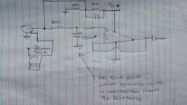
I made a simple 1st order low pass filter using a lm741 op amp just a experiment.
Now i am using a 9v Battery to power it up. The audio signal is comming from a phone with a 3.5mm jack out put.
Now when i hook up the earth lead from the 9v battery to earth on the signal wire i get no out put from my scope but when i take the 9v earth off the the signal becomes good on my scope.
I thought the earth needs to be tied up together with the audio signal earth.
Is this because the phone has its own power supply?
Here is a diagram
I added a diagram.
Attachments
.
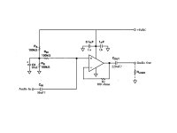
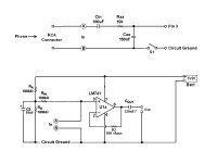
Unless I'm missing something your setup doesn't look quite right to me. The below is edited from Analog Devices AN-581, by Charles Kitchin. Here's the original: http://www.analog.com/media/en/technical-documentation/application-notes/AN-581.pdf
The question marks indicate values that I filled in at semi-random. You might need something entirely different.
.
Attachments
Here's the original
Yes, his problem is having DC on the input, and also shorting out the input with a large bypass capacitor.
This circuit is good. For a low pass filter (after the input capacitor) add a series 10k and then a capacitor to ground to set the HF cut off.
Last edited:
Is this because the phone has its own power supply?
Nope. In the circuit I posted capacitor Cin provides DC isolation between the phone and the following LM741 circuit. Similarly, capacitor Cout provides DC isolation between the LM741 and whatever might follow.
The LM741 runs at 9 volts, the phone runs at, dunno, 1.5 volts, but the different voltages don't smoke each other because they're isolated/separated by Cin.
This is a main (by no means only) reason for using capacitors: isolation of DC voltage levels in different circuits.
Having said that, I guess I have to say this: don't fall into the trap of thinking that capacitors "pass AC and block DC," which is not so. Capacitors pass changes in voltage, such as a constantly-varying audio signal, and block steady-state voltage, such as battery voltage. Whether the voltage is AC or DC doesn't enter in.
This is not something to obsess over, but I thought I should mention it.
.
Last edited:
Thank you very much for your help when i get back from work i will construct this on my bread board.
And report back. Thank you.
And report back. Thank you.
Yes, his problem is having DC on the input, and also shorting out the input with a large bypass capacitor.
This circuit is good. For a low pass filter (after the input capacitor) add a series 10k and then a capacitor to ground to set the HF cut off.
Hey mate so your saying put my low pass filter after cin on the diagram.
Also thank you snake for supplying the diagram.
Hey mate so your saying put my low pass filter after cin on the diagram.
Yes, exactly.
Yes, exactly.
Ok so i tried the circuit with the coupling capacitor both value being at 100uf at the input and output.
And still when i tie the ground with the rca (audio ground) my scope shows no reading.
But when 9v ground is off i get a good wave form. I am still trying other things.
I might need to study a bit more i think and stop watching the Cricket world cup
I think you need to show a diagram of exactly what you have when the ground is connected, and what you have when it is not. In drawing this diagram you are quite likely to find your own mistake.
Ok so i tried the circuit with the coupling capacitor both value being at 100uf at the input and output.
And still when i tie the ground with the rca (audio ground) my scope shows no reading.
But when 9v ground is off i get a good wave form. I am still trying other things.
I have to agree with DF96, but also mentioning:
Is there a load on the output? If not hook a 10k resistor across "Audio Out" in post #2. Or 1k, or something.
<< when i tie the ground with the rca (audio ground) >>
I personally have no idea what this means. You tie the ground to what, how, why? Full sentences work better.
<< when 9v ground is off >>
i guess this means you disconnect the negative side of the 9 volt batter? In that case the circuit has no power applied and does nothing, any waveform you see is coming from somewhere else. Anyway I don't know what the statement means.
Generally, notice that the circuit in post #2 is isolated by Cin and Cout, its only connection to the outside world is via the input and ouput. So these connections have to be complete with hot and cold side.
It mystifies me when you speak of "audio ground," since no such ground is shown. No clue what you mean.
.
Last edited:
I have to agree with DF96, but also mentioning:
Is there a load on the output? If not hook a 10k resistor across "Audio Out" in post #2. Or 1k, or something.
<< when i tie the ground with the rca (audio ground) >>
I personally have no idea what this means. You tie the ground to what, how, why? Full sentences work better.
<< when 9v ground is off >>
i guess this means you disconnect the negative side of the 9 volt batter? In that case the circuit has no power applied and does nothing, any waveform you see is coming from somewhere else. Anyway I don't know what the statement means.
Generally, notice that the circuit in post #2 is isolated by Cin and Cout, its only connection to the outside world is via the input and ouput. So these connections have to be complete with hot and cold side.
It mystifies me when you speak of "audio ground," since no such ground is shown. No clue what you mean.
.
Thanks for the reply guys and for helping me.
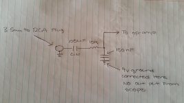
Ok so from my phone i am using a 3.5mm to rca plug
Now the rca plug has the middle prong and the outer shell.
I tied the 9v earth to the outer shell which is metal and is isolated from the middle prong.
Now when i dont connect the 9v earth on the outer shell of the rca plug i get a good reading But as soon as i supply 9v earth to the shell the scope has no reading. Thats what i meant when i said 9v ground is off. Now i thought that the battery ground should be tied to the outer shell or is this wrong?? Sorry for not explaining it better.
Now my circuit is identical to post 2.
With the exception of the 100uf caps.
Here is a diagram of what i have done after Cin.
Thanks for taking time to read this post 🙂
Attachments
You still haven't given a proper diagram. You keep omitting details, which may be important. If you knew which details were important you wouldn't need to ask us. We need a diagram of the whole thing, nothing omitted, showing exactly which connection you undo. Without that we can't help.
Sentences like "Switch is supplying Earth from 9v battery" are meaningless.
Sentences like "Switch is supplying Earth from 9v battery" are meaningless.
.
DF96 is correct, and also I understand him to suggest that drawing your circuit will help you to learn it, which is true. Not that learning a circuit you're building is some kind of requirement, it's just the way it works. By the time you have everything laid out, and otherwise figured on, you've pretty much learned the circuit whether you intended that or not.
But with all of that remaining true, I'm going to go the extra mile.
Again--and I now suspect critically--is there a load on the LM741? If not, before you do anything else put a 10k resistor across the "Out" terminals and see what happens. An oscilloscope is not a load.
Are you sure of the input from your phone? Earbud jacks on phones commonly have 3 terminals or more. Check whether you have audio from the terminals you're using.
NOTE that if the phone jack is not connected correctly, then you might have the phone's circuit ground connected to the LM741's circuit ground, which might cause odd happenings (who knows how phones are wired?).
In the schematic posted below:
Every point A is the same point, and every point B is the same point. Ca and Cb from post #2 are omitted for neatness, and as not significant to the present discussion, but leave them in. Note that each and every component is labeled, hint hint.
Depending on where switch S1 is placed in the circuit ground line it might cause odd effects. Switch the + side of Bat1, if anything.
After moving or omitting S1, the shown circuit should work. Or to put that another way, it can't not work. Leaving only the fact that, sorry, you made a wiring error. No biggee, don't feel like you're the first.
In cases like these the entire circuit costs, what, 80 cents? I personally deep 6 the whole thing and start over. (Another good reason to use NE5532s, instead of supposedly better chips, which aren't.)
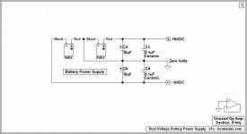
Just to toss another idea into the mix, it seems single-supply circuits are not very intuitive, and give people a lot of trouble. While the fact is that the chip will work only with dual voltages in the first place. This means that what you're really doing is going through some gyrations to create a virtual dual voltage, when it would have been easier to just hook up a second battery to begin with. Unless you want the thing in an Altoids box I personally don't see the point.
Hence the second posting below. To do it the easy--in my opinion--way, omit RA, RB, Rin, and C2. Just erase them, and all the wires that connect to them.
Then pin 7 connects to +9VDC, and pin 4 connects to -9VDC. Everything except pin 4 now shown as connecting to circuit ground instead connects to zero volts, which becomes the new circuit ground.
From post #2, Ca now connects to pin 4 and circuit ground, Cb now connects to pin 7 and circuit ground.
Just thought I'd mention that.
.
DF96 is correct, and also I understand him to suggest that drawing your circuit will help you to learn it, which is true. Not that learning a circuit you're building is some kind of requirement, it's just the way it works. By the time you have everything laid out, and otherwise figured on, you've pretty much learned the circuit whether you intended that or not.
But with all of that remaining true, I'm going to go the extra mile.
Again--and I now suspect critically--is there a load on the LM741? If not, before you do anything else put a 10k resistor across the "Out" terminals and see what happens. An oscilloscope is not a load.
Are you sure of the input from your phone? Earbud jacks on phones commonly have 3 terminals or more. Check whether you have audio from the terminals you're using.
NOTE that if the phone jack is not connected correctly, then you might have the phone's circuit ground connected to the LM741's circuit ground, which might cause odd happenings (who knows how phones are wired?).
In the schematic posted below:
Every point A is the same point, and every point B is the same point. Ca and Cb from post #2 are omitted for neatness, and as not significant to the present discussion, but leave them in. Note that each and every component is labeled, hint hint.
Depending on where switch S1 is placed in the circuit ground line it might cause odd effects. Switch the + side of Bat1, if anything.
After moving or omitting S1, the shown circuit should work. Or to put that another way, it can't not work. Leaving only the fact that, sorry, you made a wiring error. No biggee, don't feel like you're the first.
In cases like these the entire circuit costs, what, 80 cents? I personally deep 6 the whole thing and start over. (Another good reason to use NE5532s, instead of supposedly better chips, which aren't.)
Just to toss another idea into the mix, it seems single-supply circuits are not very intuitive, and give people a lot of trouble. While the fact is that the chip will work only with dual voltages in the first place. This means that what you're really doing is going through some gyrations to create a virtual dual voltage, when it would have been easier to just hook up a second battery to begin with. Unless you want the thing in an Altoids box I personally don't see the point.
Hence the second posting below. To do it the easy--in my opinion--way, omit RA, RB, Rin, and C2. Just erase them, and all the wires that connect to them.
Then pin 7 connects to +9VDC, and pin 4 connects to -9VDC. Everything except pin 4 now shown as connecting to circuit ground instead connects to zero volts, which becomes the new circuit ground.
From post #2, Ca now connects to pin 4 and circuit ground, Cb now connects to pin 7 and circuit ground.
Just thought I'd mention that.
.
Attachments
Last edited:
Oops. Of course I meant to say:
NOTE that if the phone jack is not connected correctly, then you might have the phone's hot feed connected to the LM741's circuit ground, which might cause odd happenings (who knows how phones are wired?).
NOTE that if the phone jack is not connected correctly, then you might have the phone's hot feed connected to the LM741's circuit ground, which might cause odd happenings (who knows how phones are wired?).
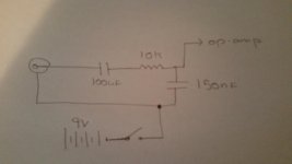
Ok guys thanks for being patient and helping me out.
I have drawn another diagram this is the circuit exactly on my bread board.
Now i tried to put a 10k load on the output but still having the same problem.
Thank you for taking time to look at this
I have drawn another diagram this is the circuit exactly on my bread board.
Now i tried to put a 10k load on the output but still having the same problem.
Thank you for taking time to look at this
Last edited:
Ok guys thanks for being patient and helping me out.
I have drawn another diagram this is the circuit exactly on my bread board.
Now i tried to put a 10k load on the output but still having the same problem.
Thank you for taking time to look at this.
I have drawn another diagram this is the circuit exactly on my bread board.
Now i tried to put a 10k load on the output but still having the same problem.
Thank you for taking time to look at this.
Attachments

You haven't shown which connection you remove in order to make the thing 'work'.
Also, was there a good reason for posting the circuit upside down? I realise that you are in Australia!
Also, was there a good reason for posting the circuit upside down? I realise that you are in Australia!
You haven't shown which connection you remove in order to make the thing 'work'.
Also, was there a good reason for posting the circuit upside down? I realise that you are in Australia!
Thats not really nice mate that your teasing me because i am Australian It was a accident that i posted it upside down. I dont know if your joking or not.
You asked me to put up a diagram of my circuit and i have. I only want help and to learn i dnt want to fight please.🙁
So do you see anything wrong with the circuit.
- Status
- Not open for further replies.
- Home
- Source & Line
- Analog Line Level
- Low pass filter circuit design