A resistor to ground on the far side of an input or output coupling capacitor is often present in well-designed equipment. It is known as a ground leak, because that describes its purpose.
The opposite is true. With no ground leak resistor the DC resistance is infinite (unless the load has a ground leak - some do not). Hence however small the leakage current there will be a DC voltage present. Adding the ground leak stops this, by presenting a suficiently low DC resistance that the small leakage current generates litttle voltage. So the choice is between a significant DC voltage without a resistor, or an insignificant DC voltage with a resistor.
No, just applying elementary circuit theory to a trivial circuit - which always works.
OK hold it, I see what you're doing now. Never mind.
.
I have a couple of questions:
1) What frequency are you putting in. ( the -3Db point is 106 hz)
2) if you are putting more than than that with the cap connected to gnd the filter is doing its job.
1) What frequency are you putting in. ( the -3Db point is 106 hz)
2) if you are putting more than than that with the cap connected to gnd the filter is doing its job.
Thank guys for your help past couple of days you guys been very helpful.
I am leaving a 2k resistor across the output.
Now I got another Question I am going to try and set some sort of gain if that is possible with this circuit.
I understand that I need 2 feed back resistors. Now when I set this gain should I see a gain in amplitude on the scope to see if its working is this correct? Is gain specific to that model op-amp so different resistor ratios is needed for different op-amp or is it one size fits all. so LM741 which I was using would it have the same value resistor as the TLO72 to set gain value of say 5.
Special thanks to BENTSNAKE & DF96 for going the extra mile and sharing there knowledge.
Last edited:
I have a couple of questions:
1) What frequency are you putting in. ( the -3Db point is 106 hz)
2) if you are putting more than than that with the cap connected to gnd the filter is doing its job.
Hi mate thanks for taking time out to read my thread.
Frequency I am putting in is 106hz you are correct. Its just for a experiment.
So when you say I am putting more than that do you mean the frequency of more than 106hz?
So your saying the effects I was getting was normal before putting the load resistor?
No, I am talking about the opposite of a bleed resistor. A bleed resistor connects in parallel with a cap, and ensures that the cap discharges to zero volts when the equipment is switched off. A ground leak resistor connects in series with a cap, and ensures that the cap charges up to the required voltage when the equipment is switched on. It is there to ensure that the cap charges - the opposite of what you say.bentsnake said:It took awhile, but I finally figured out that you're talking about a bleed resistor.
Whatever you call it, the purpose of this resistor is to stop the output capacitor from achieving a permanent fully charged state. It has nothing to do with--and cannot affect--any voltage present.
You need to do some reading on how potential dividers work. It may be confusing for newbies to hear elementary circuit theory described by you as "bizarre". You may be confused between the voltage across the cap and the voltage across the resistor.This statement is simply bizarre, because leakage current through capacitors does not cause voltage. The reverse is true, that voltage across capacitors causes leakage current to flow.
This being so, the voltage present at the downstream side of a capacitor is not affected by the amount of leakage current, because it caused that current to flow in the first place.
Yes for this purpose most opamps can be considered sufficiently similar that the same resistor values can be used. It is the ratio of the values which sets the gain. Too small values adds too much load to the opamp - this is opamp dependent. Too large resistors add too much thermal noise - how important this is depends on application and how noisy the opamp is.PKN said:Is gain specific to that model op-amp so different resistor ratios is needed for different op-amp or is it one size fits all. so LM741 which I was using would it have the same value resistor as the TLO72 to set gain value of say 5.
Yes for this purpose most opamps can be considered sufficiently similar that the same resistor values can be used. It is the ratio of the values which sets the gain. Too small values adds too much load to the opamp - this is opamp dependent. Too large resistors add too much thermal noise - how important this is depends on application and how noisy the opamp is.
So how will I know if the gain is working? Will the scope show a bigger amplitude wave form? What is the best way to check if gain is working on the circuit?
Yes. That is what voltage gain does: bigger amplitude. Measure the input voltage. Measure the output voltage. The ratio of these two is the voltage gain.PKN said:Will the scope show a bigger amplitude wave form?
Yes. That is what voltage gain does: bigger amplitude. Measure the input voltage. Measure the output voltage. The ratio of these two is the voltage gain.
ok thanks mate I will make this circuit in a couple of days and report back.
I got a team meeting at my place so I had to pack the electronics away. The GF would not let me leave it out.🙁
I am going to try and set some sort of gain if that is possible with this circuit.
I understand that I need 2 feed back resistors. Now when I set this gain should I see a gain in amplitude on the scope to see if its working is this correct? Is gain specific to that model op-amp so different resistor ratios is needed for different op-amp or is it one size fits all. so LM741 which I was using would it have the same value resistor as the TLO72 to set gain value of say 5.
For clarity on how to do it, as posted below.
The first illustration is from post #2 in this thread, re-posted only for comparison.
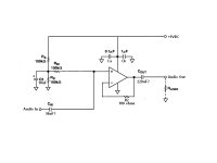
The second illustration is the same circuit with gain added. It's also updated to what I think your circuit is now, but updated or not doesn't matter, only the components with values shown in red are significant. For higher or lower gain it's usual to change R2a, leaving R2b alone--although any similar combination of resistors will work the same way.
The gain arrangement is the same for any non-inverting op amp circuit, only the pin numbers might change. Thus one size does essentially fit all, as DF96 explained.
I'm telling you, gfs just don't get it.
.
Attachments

- Status
- Not open for further replies.
- Home
- Source & Line
- Analog Line Level
- Low pass filter circuit design