I sometimes get teased by the Yanks on here. I regard it as harmless fun. No offence intended.
I could not see anything obviously wrong with the circuit. Which connection when broken restores apparently correct operation?
I could not see anything obviously wrong with the circuit. Which connection when broken restores apparently correct operation?
.
Yes he's joking. The English don't tease, they observe in a wry manner.
On the other hand, some teasing, or to that effect, might be in order when you say, "Now my circuit is identical to post 2," and then post a circuit that isn't identical to post 2. Things like this lead one to suspect that perhaps one is spinning one's wheels.
But all in the past, now moving along to present cases. The first item of business is to put that 10k resistor across the output and leave it there. Running an amplifier--which this is, even though it's a unity-gain buffer--without a load might cause strange things to happen under some conditions. We do understand that by "across the output" I mean between the terminals you have labeled "scope."
First of all, a question: How familiar are you with breadboards? You do know that some holes connect vertically but not horizontally, others connect horizontally but not vertically? Don't think I'm calling you stupid, you're on the other side of the planet from me, how am I supposed to know what you do or don't know?
After that an observation: It seems the signal from the phone is just going straight through your circuit when ground is disconnected, but is shorted out when ground is connected. Or to that effect, kinda.
Time to quit guessing and start troubleshooting. Past time, actually. And since you have a scope the situation is near-optimum. Use the scope for signal tracing, which is what it's for in the first place. One of the things it's for.
Throughout all of what follows put a finger on the phone, the IC, and the battery at different times. None should get hot. If they do then disconnect the battery, and do it quick.
Hook up the phone. Hook the scope probes to the INPUT terminals at the RCA connector, black to ground. HAVE THE GROUND SIDE OF YOUR CIRCUIT DISCONNECTED as you have before, the only way you've gotten an output from your circuit. Power up the circuit (with the ground side still disconnected).
You have a scope trace from the phone, yes? Disconnect the phone. Still have a trace? Then the scope is showing you something unknown.
But if the scope trace disappears (which is expected) then reconnect the phone. Supposedly you again have the same trace, which we're now [fairly] certain is coming from the phone.
Leave the black probe connected to the input ground at all times. The red probe is now hand held. Referring to my circuit in post #15.
Probe the input side of Cin, then the output side. Still have a trace? Realize that at the output side of Cin the phone signal is riding on 4.5VDC, so the trace will jump (depending on how you have your scope set).
Probe the input side of Raa, then the output side. Still have the same trace? Note that you probe BOTH the input and output sides of every component, because this also checks the conductors between components.
Probe pin 3 of the IC. I think you're getting the picture. You trace the signal from the phone through the circuit, hence "signal tracing." Continue on through the circuit.
Quite likely this will tell you that the output is the same as the input, which says the signal from the phone is just traveling though the circuit, which doesn't tell you much.
Sooo...black probe still connected to the RCA connector ground side, red probe still in your hand, now connect the circuit ground.
Again trace the signal, starting at the RCA connector. Trace through, finding out where the signal disappears.
If the signal disappears at the RCA connector when you connect circuit ground, then there's a catastrophic short in your circuit that's shorting everything to ground. Ordinarily a bad component is not the first thing to expect, but maybe the LM741 is internally shorted. In any case the only solution is to find the short.
REMEMBER to disconnect the phone, you don't want it running with the output shorted (although with phones, who knows).
.
Last edited:
Thanks guys for all your input.
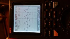
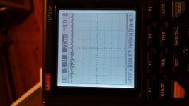
Ok so bentsnake your explanation is correct the signal is going straight through but when ground is connected circuit wont produce the 100hz wave form. I tried to trouble shoot and when ground is connected there is only near 4v showing at rca output see diagram.
I have added the scope reading please see attachment.
The out put was showing close to 4v when battery ground was connected so i thought the coupling capacitor was no good. So i went and bought new ones but same problem.
1st photo with wave form no battery ground connected
2nd photo battery ground connected near 4v no wave form
Sorry about the photo being sideways.
Attachments
Last edited:
Two likely causes:
1. you haven't built the circuit you think you have built.
2. it is oscillating.
Given typical breadboard layouts either is possible. Have you added any supply pin decoupling? It is possible that modern 741 have much more HF gain than the originals.
1. you haven't built the circuit you think you have built.
2. it is oscillating.
Given typical breadboard layouts either is possible. Have you added any supply pin decoupling? It is possible that modern 741 have much more HF gain than the originals.
in case of the headline topic (low pass foilrer design) this thread is of interest:
http://www.diyaudio.com/forums/analog-line-level/268053-low-pass-filter-subwoofer.html (post#5).
In case of the actually mentioned issues you will need basically articles and papers/books concerning the audio design of op-amp line- and filter circuits.
http://www.diyaudio.com/forums/analog-line-level/268053-low-pass-filter-subwoofer.html (post#5).
In case of the actually mentioned issues you will need basically articles and papers/books concerning the audio design of op-amp line- and filter circuits.
🙂
I have not added any coupling capacitor on the power supply line if this is what your asking.
I will do this tomorrow. FYI everyone I am using a 9v battery the rectangle one you get from the shops just thought I add that in lol.
Two likely causes:
1. you haven't built the circuit you think you have built.
2. it is oscillating.
Given typical breadboard layouts either is possible. Have you added any supply pin decoupling? It is possible that modern 741 have much more HF gain than the originals.
I have not added any coupling capacitor on the power supply line if this is what your asking.
I will do this tomorrow. FYI everyone I am using a 9v battery the rectangle one you get from the shops just thought I add that in lol.
Last edited:
Add supply rail decoupling. The battery is not good at supplying changes in current.
The decoupling ONLY works by supplying CHANGES in current.
Coupling capacitors are not the same as decoupling capacitors.
The decoupling ONLY works by supplying CHANGES in current.
Coupling capacitors are not the same as decoupling capacitors.
Add supply rail decoupling. The battery is not good at supplying changes in current.
The decoupling ONLY works by supplying CHANGES in current.
Coupling capacitors are not the same as decoupling capacitors.
Thanks for your input and advice on the right terminology to use.
Connect a ~10k resistor across the output as suggested earlier, then output DC should remain close to zero. You can do the math on how long it takes to discharge a 100µ capacitor by a typical 1 Megohm general purpose scope input.
Speaking of time constants, 100k * 470µ is fairly long, too. How long did you wait after powering the circuit up?
If you want to know whether an opamp circuit is working properly, compare voltages at the inverting (-) and noninverting (+) input terminals. They should be within a mere 25 mV or so, and a direct measurement may be necessary (but might upset the circuit). That's ideal opamp equations applied.
Output voltage (pre coupling cap) should also be the same as noninverting input voltage here, a little less than half supply DC (4-ish V seems about right, as npn input bias current in the µA741 would drag things down somewhat).
Last edited:
.
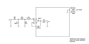
Pop quiz: How complicated is this circuit?
Hint: Not so very.
For extra credit: Measure the battery voltage, which is found to be approximately 7 volts. This reduction in voltage is caused by extreme loading of the battery due to a partial short to ground. Right now my money's on the LM741 being partially shorted.
To skip the final: Pare your circuit down to the indicated, noting that there are three--count 'em three--components in the audio circuit (the rest are in the power supply circuit).
Course requirements for a master's follow.
.
Pop quiz: How complicated is this circuit?
Hint: Not so very.
For extra credit: Measure the battery voltage, which is found to be approximately 7 volts. This reduction in voltage is caused by extreme loading of the battery due to a partial short to ground. Right now my money's on the LM741 being partially shorted.
To skip the final: Pare your circuit down to the indicated, noting that there are three--count 'em three--components in the audio circuit (the rest are in the power supply circuit).
Power up and see what happens. Do this with the phone connected, and also not connected.
Then remove C2 and again see what happens. Again with the phone connected, and also not connected.
This is still putting your finger on the LM741. If anything works, the chip heating up probably indicates oscillation. If nothing works, the chip heating up probably indicates a partial short. The chip not heating up indicates nothing.
I'm doubling down on nothing will change due to the LM741's being toast.
Course notes: Obviously there's either a wiring mistake, a bad component, or both. Or, as DF96 pointed out, oscillation, but that's not my personal first choice.Then remove C2 and again see what happens. Again with the phone connected, and also not connected.
This is still putting your finger on the LM741. If anything works, the chip heating up probably indicates oscillation. If nothing works, the chip heating up probably indicates a partial short. The chip not heating up indicates nothing.
I'm doubling down on nothing will change due to the LM741's being toast.
Course requirements for a master's follow.
.
Attachments
Master's Degree in Two Batteries
.
This has nothing to do with the circuit in the first part of this thread. This is the next step, in my opinion a step toward reason.
WHY - THE AMP: The single-supply circuit in this thread is perfectly OK for what it is, which is essentially a stompbox circuit to be used with electric guitars. It's fine for that, but probably not ideal for other uses.
More important to the present point, the power supply is a "cookboook" design intended to serve the greatest number of DIYers with the simplest possible circuit. Simplicity is good, but the one-size-fits-all design places restraints on resistor and capacitor values.
Again this is OK, but it does make the design a one-trick pony. Good for wailing on your Strat, but maybe not a first choice for anything else. Here's more single-supply information: http://www.ieee.li/pdf/essay/single_supply_op_amp_design.pdf
WHY - THE FILTER: Required is a low-pass filter coming in at around 1,000Hz. Ordinarily this is simple enough, but in this case the filter is on an input circuit, so there's also a DC blocking capacitor, which is considered mandatory. Two capacitors being present creates, in effect, two filters in series ("cascaded filters").
WHY - TWO FILTERS: A single high- or low-pass filter is trivial, but cascaded filters are another story. The math can become painful. However, non-masochists fall back on the "times ten" rule of thumb, which requires that cascaded filters must have their operating points separated by a factor of ten. For example, a 100Hz filter must be followed by a filter operating at no less than 1,000Hz, or the other way around.
Obviously this places restraints on resistor and capacitor values. While at the same time a single-supply circuit also places restraints on resistor and capacitor values. Can you say uh-oh?
Anybody so inclined should feel free to work out the math for the single-supply circuit in this thread. Enjoy.
A SOLUTION: Or alternately, just ignore the whole thing. Also use fewer parts, and quit reaching around your elbow to scratch your nose. The proposed circuit does that.
Just to mention it, the correct way to do this would be to feed the audio first to a buffer, from the buffer to the low-pass filter, and then to another buffer or gain stage. All of this being done to isolate the filter(s) from other circuit components that could change the filtering value(s). But c'mon.
.
.
This has nothing to do with the circuit in the first part of this thread. This is the next step, in my opinion a step toward reason.
WHY - THE AMP: The single-supply circuit in this thread is perfectly OK for what it is, which is essentially a stompbox circuit to be used with electric guitars. It's fine for that, but probably not ideal for other uses.
More important to the present point, the power supply is a "cookboook" design intended to serve the greatest number of DIYers with the simplest possible circuit. Simplicity is good, but the one-size-fits-all design places restraints on resistor and capacitor values.
Again this is OK, but it does make the design a one-trick pony. Good for wailing on your Strat, but maybe not a first choice for anything else. Here's more single-supply information: http://www.ieee.li/pdf/essay/single_supply_op_amp_design.pdf
WHY - THE FILTER: Required is a low-pass filter coming in at around 1,000Hz. Ordinarily this is simple enough, but in this case the filter is on an input circuit, so there's also a DC blocking capacitor, which is considered mandatory. Two capacitors being present creates, in effect, two filters in series ("cascaded filters").
WHY - TWO FILTERS: A single high- or low-pass filter is trivial, but cascaded filters are another story. The math can become painful. However, non-masochists fall back on the "times ten" rule of thumb, which requires that cascaded filters must have their operating points separated by a factor of ten. For example, a 100Hz filter must be followed by a filter operating at no less than 1,000Hz, or the other way around.
Obviously this places restraints on resistor and capacitor values. While at the same time a single-supply circuit also places restraints on resistor and capacitor values. Can you say uh-oh?
Anybody so inclined should feel free to work out the math for the single-supply circuit in this thread. Enjoy.
A SOLUTION: Or alternately, just ignore the whole thing. Also use fewer parts, and quit reaching around your elbow to scratch your nose. The proposed circuit does that.
Just to mention it, the correct way to do this would be to feed the audio first to a buffer, from the buffer to the low-pass filter, and then to another buffer or gain stage. All of this being done to isolate the filter(s) from other circuit components that could change the filtering value(s). But c'mon.
.
Attachments

Last edited:
Hey guys me again. So today I went and bought a new op-amp TLO72CN asked for TLL071 But any way.
Hooked everything up today and it worked! I got the load resistor on the out put 10k.
So the I had a faulty op amp. The other thing I changed was the power supply 12-14v DC 3amp max.
Now I understand the 10k resistor is used as a load on the output. Now when I hook this up to a amplifier that becomes the load so do I keep this 10k across the out put or is it safe to remove it. if I keep it does it matter. I am not sure how the input of a amplifier is wired up.
Thanks guys for helping me and reading my thread. 🙂
Hey guys me again. So today I went and bought a new op-amp TLO72CN asked for TLL071 But any way.
Hooked everything up today and it worked! I got the load resistor on the out put 10k.
So the I had a faulty op amp. The other thing I changed was the power supply 12-14v DC 3amp max.
Now I understand the 10k resistor is used as a load on the output. Now when I hook this up to a amplifier that becomes the load so do I keep this 10k across the out put or is it safe to remove it. if I keep it does it matter. I am not sure how the input of a amplifier is wired up.
Fixed that puppy, yay you!
<< I understand the 10k resistor is used as a load on the output. >>
Correct. The 10k resistor was only to have some load--any load--on the output. No other purpose.
<< do I keep this 10k across the out put or is it safe to remove it. >>
My thinking is the opposite of DF96's, I'd just remove the 10k resistor and be done.
Or it might be found that removing the 10k resistor causes the whole setup to suddenly stop working, in which case I'd replace 10k with a 2.2k resistor. Or heck, even with a 2k potentiometer, which then becomes a volume/level control.
But I don't know DF96's reasoning so I'm open to argument.
<< I am not sure how the input of a amplifier is wired up. >>
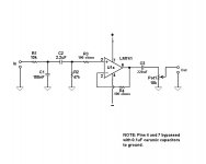
Neither am I, but it probably includes C2-R2 in post #31. Just because pretty much every amp in the world is wired that way.
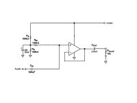
But lacking certainty you MUST include a capacitor on the TL072's output (220uF or whatever). This is because you're running a single-voltage power supply, so the the output pin of the TL072 is at approximately +6VDC, which is not to be fed to the amp's input.
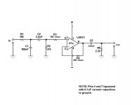
PS you're running a TL072 so there's an unused section of the op amp? A floating section can cause problems under some conditions, so best to terminate it as shown in the second illustration in post #31.
.
As I said (and so did sgrossklass) the 10k is a ground leak, to ensure no DC at the output.bentsnake said:But I don't know DF96's reasoning so I'm open to argument.
It also adds an AC load, but that is unlikely to change anything.sgrossklass said:Connect a ~10k resistor across the output as suggested earlier, then output DC should remain close to zero.
if you want to download <a href="http://pdfbookspot.com/"> electronics books </a> you can download this website.
...the 10k is a ground leak, to ensure no DC at the output...
Actually no it's not, it's a load resistor. You mighty recall that I'm the one who said add it, so I get to say what it is.
Either way, calling something by a name doesn't explain anything, it just repeats in different words. So it's not an argument, it's an unsupported assertion.
But going on from there, this "ensure no DC" view seems to me backward. Instead you're creating a DC voltage at the output.
The only DC voltage available would be from leakage through the output capacitor, which is to say current flowing through the capacitor. We're talking milli-, or more likely microamps.
Regardless of the value, and assuming no following stage, this very small current would ordinarily be shunted to ground. Current at ground is zero current, thus zero voltage.
But if a resistor is present, then the leakage current flows through the resistor. Thus a voltage is developed, appearing at the capacitor side of the resistor. So as before DC is not prevented, it's assured.
This sounds a bit like mixing digital circuits with audio circuits, which doesn't always work. In any case thanks for commenting, but I find myself sticking with my original recommendation in post #34.
.
Last edited:
A resistor to ground on the far side of an input or output coupling capacitor is often present in well-designed equipment. It is known as a ground leak, because that describes its purpose.bentsnake said:Actually no it's not, it's a load resistor. You mighty recall that I'm the one who said add it, so I get to say what it is.
Either way, calling something by a name doesn't explain anything, it just repeats in different words. So it's not an argument, it's an unsupported assertion.
The opposite is true. With no ground leak resistor the DC resistance is infinite (unless the load has a ground leak - some do not). Hence however small the leakage current there will be a DC voltage present. Adding the ground leak stops this, by presenting a suficiently low DC resistance that the small leakage current generates litttle voltage. So the choice is between a significant DC voltage without a resistor, or an insignificant DC voltage with a resistor.But going on from there, this "ensure no DC" view seems to me backward. Instead you're creating a DC voltage at the output.
The only DC voltage available would be from leakage through the output capacitor, which is to say current flowing through the capacitor. We're talking milli-, or more likely microamps.
Regardless of the value, and assuming no following stage, this very small current would ordinarily be shunted to ground. Current at ground is zero current, thus zero voltage.
But if a resistor is present, then the leakage current flows through the resistor. Thus a voltage is developed, appearing at the capacitor side of the resistor. So as before DC is not prevented, it's assured.
No, just applying elementary circuit theory to a trivial circuit - which always works.This sounds a bit like mixing digital circuits with audio circuits, which doesn't always work.
.
It took awhile, but I finally figured out that you're talking about a bleed resistor.
Whatever you call it, the purpose of this resistor is to stop the output capacitor from achieving a permanent fully charged state. It has nothing to do with--and cannot affect--any voltage present.
After that I put all else aside in favor of...
This statement is simply bizarre, because leakage current through capacitors does not cause voltage. The reverse is true, that voltage across capacitors causes leakage current to flow.
This being so, the voltage present at the downstream side of a capacitor is not affected by the amount of leakage current, because it caused that current to flow in the first place.
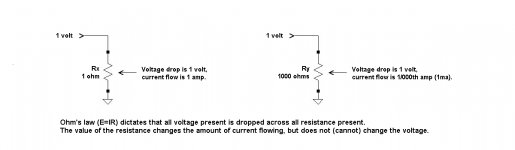
At which point I realize not a word of this will be believed by certain. Therefore I post the below illustration for the benefit of passes-by, and go on to actually useful stuff.
.
It took awhile, but I finally figured out that you're talking about a bleed resistor.
Whatever you call it, the purpose of this resistor is to stop the output capacitor from achieving a permanent fully charged state. It has nothing to do with--and cannot affect--any voltage present.
After that I put all else aside in favor of...
...however small the leakage current there will be a DC voltage present. Adding the ground leak [resistor] stops this, by presenting a suficiently low DC resistance that the small leakage current generates litttle voltage.
This statement is simply bizarre, because leakage current through capacitors does not cause voltage. The reverse is true, that voltage across capacitors causes leakage current to flow.
This being so, the voltage present at the downstream side of a capacitor is not affected by the amount of leakage current, because it caused that current to flow in the first place.
At which point I realize not a word of this will be believed by certain. Therefore I post the below illustration for the benefit of passes-by, and go on to actually useful stuff.
.
Attachments
Last edited:
.
Actually getting to cases--nice change--here's what to do at the output. One way is as good as the other, single- or dual-voltage power supply doesn't matter. As a matter of fact nothing to the left of C3 matters.
.
Actually getting to cases--nice change--here's what to do at the output. One way is as good as the other, single- or dual-voltage power supply doesn't matter. As a matter of fact nothing to the left of C3 matters.
.
Attachments
Last edited:
- Status
- Not open for further replies.
- Home
- Source & Line
- Analog Line Level
- Low pass filter circuit design