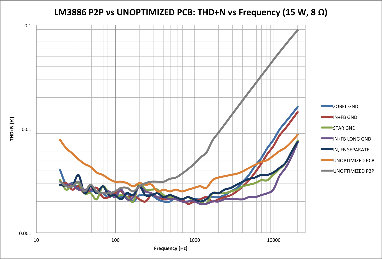
Tom, excellent that you have done this graph, http://www.diyaudio.com/forums/atta...-point-point-data-lm3886_groundcomparison.png. In particular, showing how getting the treble to perform well requires great attention to detail ...
Thanks,
Thanks,
I don't doubt that it works, i.e. that the amp can move a speaker cone, but you will not get the performance you think you're getting. Specifically, you will get a significant rise in THD above 1 kHz due to the spider ground. You'll be hard pressed to even meet the data sheet performance of the LM3886 with that layout, even though it's a composite amp.
There are several other issues, but the grounding is the main one as far a THD is concerned.
You can get an idea of the layout's impact on the performance of an amplifier in this thread: http://www.diyaudio.com/forums/chip-amps/252436-lm3886-pcb-vs-point-point-data-3.html#post3846783
The images attached are the top and bottom layers from the .zip file posted above (converted to PNG).
~Tom
Thanks for your interest Tom. What about the fact that as it's a bridged amp, there's "no current" in ground path ? And look at all the decoupling caps on big current trace.
If i remember what i've readen/translated from the bato mm forum, it solved those kind of issues... The amp is said to be usable to 136khz.
1khz seems pretty clean (it's not my measurement) :

I'll try myself higher some square waves tests (1khz-5khz-20khz-50khz) with real speaker (8ohm 12" sub high inductance Le>3mh ) and report output form just to see. I don't have distortion measurement tools. And not sure my built is the cleanest (it's my 2nd smd soldering) since i got problem with "1% resistor" that were more in the 10% range, and i made cap order error too (50v for decoupling, instead of 100v so i solved it, far from ideal, soldering them in crappy serie/parrallel).
Last edited:
If the amp works well, you should be able to push any audio analyzer on the market to the limit. My modulus-86 Rev. 2.0 pushes the limit of my Audio Precision APx525 analyzer. The APx525 is the second-best audio analyzer in the world... The only analyzer that's appreciably better is the APx555, starting at $30000+. You should be able to get a THD below -115 dB (0.0003 %). And no, you will not see a THD that low on an oscilloscope shot.
To measure the quality of the layout, perform a THD vs frequency sweep at the max output power. If you have a good layout, the curve will be nearly flat. A bad layout will cause the THD to degrade by an order of magnitude or more at 20 kHz compared with 1 kHz. With a poor layout, you can wreck the performance of the LM3886 itself, as I did in this experiment: http://www.diyaudio.com/forums/chip-amps/252436-lm3886-pcb-vs-point-point-data-3.html#post3846783
~Tom
I don't have those kind of measurement tools, and electronic is just a little hobby for me.
So what do you think about the fact that there's no big current in ground path of bridged amp on distortion ?
Don't you feel your pcb vs p2p test results would be different with a bridged amp ?
So what do you think about the fact that there's no big current in ground path of bridged amp on distortion ?
Don't you feel your pcb vs p2p test results would be different with a bridged amp ?
Last edited:
Member
Joined 2009
Paid Member
Here a little link to start about it (pcb version 0.8), uploaded below gerber and bom of v1. Just finished one, it works like a charm 🙂. Got 5 pcb left if interested.
It looks very nice to me. I was hoping for a schematic mostly to see what new knowledge I can learn from it as it appears to be well regarded and since it is not commercial there are few secrets. The pcb looks nice but I rarely build an existing design because I don't learn from it.
It's interesting to think about the consequences of a bridged amp, this is new to me and as you say, it means a different treatment of the ground may be in order.
So what do you think about the fact that there's no big current in ground path of bridged amp on distortion ?
I know the lack of a ground plane will cause an increase in distortion. The lack of a ground plane will also cause higher mains hum. I know this because I've measured it.
Don't you feel your pcb vs p2p test results would be different with a bridged amp ?
I don't. Physics is physics after all. The layout-dependent distortion mechanism happens because a signal-dependent error voltage develops across the ground connections. To minimize the distortion, you have to minimize this error voltage. The error voltage is an I*R drop. The current, I, is the mostly from the return path of the load current. The only variable we have control over with the layout is R - the resistance of the ground path (or the impedance of the ground path at AC).
To minimize the ground impedance we need to minimize the resistance and the inductance. Wider, thicker trace -> lower resistance. Wider, thicker trace -> lower inductance. The widest trace you can get is a plane. Hence, to minimize the ground impedance, you need to use a ground plane.
You can simulate this by modeling the impedance of the ground network using lumped elements (L, R, C) and injecting an error current into the ground net starting at the load return ground point. Estimate the impedance of the traces/planes using one of the many PCB parasitics calculators available on-line.
I went through this exercise when I designed the Modulus-86 and I backed up my simulations with lab experiments. That's how I know the impact of the layout on the THD performance.
In a bridged configuration, you may get lucky and get some harmonic cancellation of the even order harmonics in a poor layout. However, the stars will have to align perfectly for that to happen, and in my experience, cancellation schemes usually make the performance worse. You will not get any cancellation of the odd-order harmonics, so they will be significantly worse with a poor layout than with a good layout.
Bottom line: The layout is part of the circuit and should be treated as such. I suggest simulating the layout. It's actually not that difficult, but it does stretch your thinking a bit. At least that was my subjective experience.... 🙂
I understand that not everybody can justify the expense of fancy test gear. I squirmed quite a bit when I wrote the check for the APx525. There are less expensive options out there. The Quaint Asylum QA-400 is probably the most interesting option. Its headline specs are quite good. If you can get all your measurements to align with the sweet spot of the instrument, you can take some pretty amazing measurements with that box. You certainly get your $400 worth...
~Tom
Last edited:
Hi to all,
some comments on this matter, I'm the author of BatoMM PCB V1.0 and those oscilloscope shot. Design of amplifier is done by Macola, my colleague which have enormous experience in precise analog processing in more complex (industrial) fields than audio.
At a moment, I don't have high-precision measurements (AP) of BatoMM amplifier. We done just basic testing with Arta software trough TC Electronic Impact Twin connected via differential attenuator realized with 0.05% resistors and with pure resistive load.
The results are (for me) quite impressive and in general THD is LOWER than TC's THD = we was not able to measure THD with this setup!
I'm not saying that BatoMM is best-in-the-world amplifier, but for such small, simple and compact amplifiers results are quite good.
Amplifier is very very well compensated, somehow tricky if you don't know the smallest details/behaviors of LM3886 as Macola knows. Also, with it's assistant I design PCB and applied all known to me technics/best practice for PCB layout.
Major details are related to strong wide-bandwith decoupling of LM3886 chips which is almost pushed to practical limit, it is not possible to put more capacity closer to it's power supply pins. Similar are done with LME and in addition to that we advice to put several different capacitors (10n + 100n + 1u) on single/same pad on PCB.
Next details are related to resistors placements and again this is done according to best practice, it is not the same if you put resistor "here or there", only one approach is valid and practical results can be seen on PCB V1.0.
Next, in order to get smaller resistance and inductance of PCB tracks, I have "doubled" power supply tracks with parallel tracks on two layers and due practical (and finical) reasons we didn't want to use ticker copper.
The last thing regarding star grounding, as there is no major current flow trout GND (only about constant 20mA for powering 12V zener diode + few mA for mute/stand-by pins) the influence on audio signal is almost neglected. Probably that can be measured with some APs but our goals was to design the compact amplifier which can give us best ratio of spent money on components versus resulting sound quality.
Input stage and related R/C components occupied only about 10mm^2 and that area is ground-planed on other side of PCB and by my opinion there is no other ways to improve that.
PS: I have experience about 25 years in designing industrial automation staff and RF circuits, I'm not "audiophile", I simple enjoy building small, robust and when talking about audio, great sounding amplifiers, beside that I enjoy music much more than hunting for 3th, 4th or 5th decimal of THD 😉
Best regards,
Miki
Last edited:
PS2: Macola and me have done several 100kW resonant power inverters, and believe me star grounding is something that you can't omit. When you get about several hundreds volts of voltage drop on pice of conductors with length of "just" about 30cm with diameter of 2-3cm you will get what I'm talking about (hint 2-5kA!!!). Absolutely same things happens in smaller conductors and mA ranges but of course values are proportionally smaller ...
A single ground point for the system and star grounding are surely 2 completely different things?
Maybe I did't explain well, the point is in that understanding of current flows and treading every conductor as "resistor+inductor+antenna" is crucial for proper design, whatever values of current flows trough it.
Using star/single point wiring is method to null potentials and preventing current flow where we with intention do not want to flow.
In those mentioned inverters, neglecting that can lead to very serious problems while in audio can lead to other problems mostly related to hum/noise, distortions and instability.
Last edited:
I have little experience of very high power stuff beyond some 70kva thyristor puck stacks that were a lab session at uni decades ago, but everything I have read on precision analogue (which a composite amp is) used ground planes, with careful cuts where needed.I've not seen a non-audio precision application where a star earth on the pcb gave better performance than a well implemented ground plane. I would be interested in understanding your secrets here.
Maybe I did't explain well, the point is in that understanding of current flows and treading every conductor as "resistor+inductor+antenna" is crucial for proper design, whatever values of current flows trough it.
Using star/single point wiring is method to null potentials and preventing current flow where we with intention do not want to flow.
In those mentioned inverters, neglecting that can lead to very serious problems while in audio can lead to other problems mostly related to hum/noise, distortions and instability.
Not everybody agrees to that - here is a view from a pro.
http://www.hypex.nl/docs/papers/The G Word.pdf
Jan
Hi Jan, tnx for this article which is finally free for download 😉
I have builded that pre-amp, also we organized GB for PCBs, very nice design.
But honestly, I personally don't have such GND issues nor anyone who build this amp (according to feedbacks from users), with or without Bruno's pre-amp, at least problems which can be heard on BatoMM, maybe some measurements can show difference but as mentioned, I don't have access to AP instruments.
If anyone have access to such instruments and BatoMM amp, I would be thankful to see measuring results (especially with and without remote sensing FB), whatever they will show. I don't have any problems with that as I don't sell anything. BatoMM is open hardware design and any advice are welcome.
Next, in order to get smaller resistance and inductance of PCB tracks, I have "doubled" power supply tracks with parallel tracks on two layers and due practical (and finical) reasons we didn't want to use ticker copper.
That's commendable, however, you missed the opportunity to minimize the inductance and resistance by using a ground plane for the return. That will limit your performance.
The last thing regarding star grounding, as there is no major current flow trout GND (only about constant 20mA for powering 12V zener diode + few mA for mute/stand-by pins) the influence on audio signal is almost neglected. Probably that can be measured with some APs but our goals was to design the compact amplifier which can give us best ratio of spent money on components versus resulting sound quality.
That may be the case at DC, but at >1 kHz you will have significant voltage drop across the traces due to their inductance. This will limit the performance of your amplifier. This could have been avoided by using a ground plane. I mean... You pay for the copper anyway. Why not use it? If you're going through the trouble of designing a composite amplifier, why not aim for the best performance possible?
I was able to quantify the impact of the ground plane using my HP8903A audio analyzer on a naked LM3886. The HP8903s are not that expensive...
I agree that to some extent chasing the last zero on the THD is largely of academic interest. I would argue, though, that you will not be able to eek out the last bit of performance unless you understand the system. Also, if you design a composite amp to get better performance, why not optimize the layout as well? Other than the time spent thinking through the problem, it doesn't cost you anything to optimize the layout.
~Tom
Sounds like what was measured was cancellation of distortion products. In which case it's easy enough to determine the approximate level of the cancelling terms; it varies with phase but more cancellation necessarily implies worse performance from the BatoThe results are (for me) quite impressive and in general THD is LOWER than TC's THD = we was not able to measure THD with this setup!
If anyone have access to such instruments and BatoMM amp, I would be thankful to see measuring results (especially with and without remote sensing FB), whatever they will show. I don't have any problems with that as I don't sell anything. BatoMM is open hardware design and any advice are welcome.
I'll be happy to measure the BatoMM as long as you're willing to pay the shipping fees and buy me a steak dinner (or provide its monetary equivalent... 🙂)
~Tom
Hi,The full version original thread need to be translated from here, but it s a lot more technical : Bato MM-Amp (LM-most by macolakg) : Dokumentacija It seems that the original forum gone down and all was copied on yu3ma s forum. V1 smd pcb is very cool...
Can you put here all documentation? New account registrations is disabled on that forum.
thank you in advance
- Home
- Amplifiers
- Chip Amps
- LM3886 & LME49720 composite amp