Hi,
just a question: you use the other part of the LME49720 for the DC-servo. But this is far not optimal for this application! After simulation you have not benefit with this IC. You should try the OPA2277 e.g., or similar with low bias current optimal for DC...
just a question: you use the other part of the LME49720 for the DC-servo. But this is far not optimal for this application! After simulation you have not benefit with this IC. You should try the OPA2277 e.g., or similar with low bias current optimal for DC...
Hi,
just a question: you use the other part of the LME49720 for the DC-servo. But this is far not optimal for this application! After simulation you have not benefit with this IC. You should try the OPA2277 e.g., or similar with low bias current optimal for DC...
Read the first few lines of the thread.
Of course... Ideas are welcome!
Attachments

Last edited:
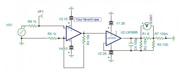
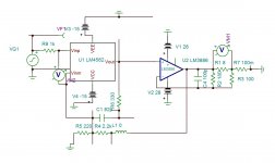
Could somebody tell me what's the real purpose of the (in my case) C6-C7 capacitor in the feedback path of the opamp?
Of course... Ideas are welcome!
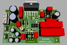
It seems you are building Modulus -86 Lite🙂
- form HF input RC filter with R3 + C to ground in the range of 100-220pF, R3=2k, move R9 on the right side of R3
- keep only C6=~330pF, C7 in parallel is surplus (it compensates U2 and shape HF response of composite amp
- place local decoupling caps 100nF on U2/U3 supply pins
- C1=150-330pF, C35 not needed, R1=330Ω, C2=150-220pF, C13=27-39pF, C14=100uF non-polar electrolyte cap, C9/C12=22uF, C8/C11=1-4.7uF MLCC
- place LR (10Ω/3W +0.7uH) cell on the amplifier output
Of course, these suggestions should be simulated/scoped to verify proper value/operation.
You don't need overall feedback if you use current feedback on the output. The LM3886 is perfectly stable with a gain of 2.8 . The output impedance becomes capacitive at high frequencies, making it inert to oscillations ,hence no need for Zobel. The frequency response is extended to 5.5Mhz ,The distortion reduced by 7 fold (modulus 86 is 3 fold).
You only need to amplify it by 3-10 using a driver amp. I advise you the TPA6120A2 that you can buy mounted module for 3$ as headphone amp to modify the gain.
PS The 0.1 ohm must be non inductive , either BPR56 or 10x1 ohm 1/2W thick leads.
You only need to amplify it by 3-10 using a driver amp. I advise you the TPA6120A2 that you can buy mounted module for 3$ as headphone amp to modify the gain.
PS The 0.1 ohm must be non inductive , either BPR56 or 10x1 ohm 1/2W thick leads.
Attachments
Last edited:
Thanks a lot!! 🙂
Yes, the "Modulus" gave me really some ideas...
The posted schematic is not complete, the PSU section for the opas (LM317/337 and decoupling caps) are not illustrated yet.
The C6 is intresting: if it is small (<100pF), there is a remarkable peak in the transfer characteristic. If it is too large (>300pF), the S/N performance will be strongly degraded. Best option should be w/o this cap, but I think ther must be there because of overall stability of the circuit.
R1=330Ω seems to be very small, I'll leave it first.
C14=10uF MKS or 1uF MKP is just fine for me. I would never take an electrolitic there. I've an active system, so this cap can be fine tuned depending on for which driver (tweeter, woofer) I use the amp in terms of low-pass -3dB point. But if the DC-servo is on, the cap is anyway out of operation.
I'll leave the output LR. It takes a lot of PCB place, and the amps will drive the speakers directly w/o passive xover. It means, there is no capacitive load, only the 3-4m lsp cable. If needed it can be upgraded (e.g. at the lsp terminals).
Attached a simulation file for experimenting...🙂
Attachments
Last edited:
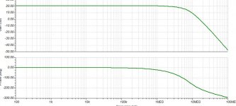
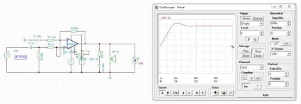
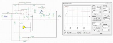
Open loop response of your amp with R1=1.5k for closed loop flat response 1Mhz. Transient response for 10v 10khz , same for mine .
Yes you get about the double Dis+N of LM4562 in total pulling Tomchr red to charge you . The sound on the other hand will not be better than lm3886 with gain 20 as it has the same transient .
Yes you get about the double Dis+N of LM4562 in total pulling Tomchr red to charge you . The sound on the other hand will not be better than lm3886 with gain 20 as it has the same transient .
Attachments
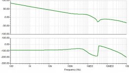

Sorry, but I don't really understand your measurements. What do you make with the scope? Step response? What are the conclusions (with numbers please!)?
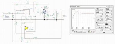
That's it, w/o C1 the circuit will oscillate!!! Like simulation 130pF is an absolute minimum to get it stable.
It is a sensible game to find the right balance between stability and performance...
I tend to make this cap in the range of 500-1000pF. It makes a minor degradation in S/N performace, but the amp remains stable and the step response is excellent.
It is a sensible game to find the right balance between stability and performance...
I tend to make this cap in the range of 500-1000pF. It makes a minor degradation in S/N performace, but the amp remains stable and the step response is excellent.
Attachments
Last edited:
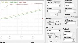
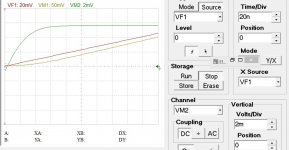
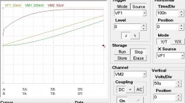
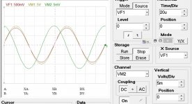
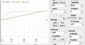
Since I am not familiar with TINA, could you place as a load 8Ω in parallel with 1uF (instead of speaker) and repeat the step response in +/- directions?
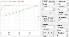
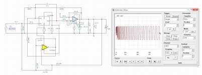
Op amps are integrator transfer function . The output signal in open loop gets delayed (lagged) by 90° after its F-3 . When the loop is closed the feedback must provide the opamps input the derivative function, so that after integrated by the transfer function reaches the output at 0° phase . Now , if you apply a sinusoidal signal the feedback at the start must rise immediately to its maximum. In reality it cannot create volts from zero error , it must let the output blinded and wait according the speed of the amp to reach the required maximum 90° phase advance . Note that if the open loop frequency responce is wide bandwith , than the phase shift required would be only few degrees , requiring lower voltage step to start . I post bellow the simulation of Lm3886 with 1k ,10k feeback resistors , with 10Vp 10khz Vp1 =input VM1=output VM2=+/-input of opamp. On time magnified plot you see the output has about 150ns flat (blinded) output. While the amp is blinded waiting the rise of the input signal across the inputs ,multiple signals although less than 20khz reach ,concecutively with narrowly spaced in time, the amp will produce a distorted sound instead of producing highly pleasing sound as occurs in multiple brass orchestras . Listen to the following two music , you will understand .
https://www.youtube.com/watch?v=9IlT2yeOJ0g.
https://www.youtube.com/watch?v=1PdcmFvZvuI&t=570s
By designing a feedback amp if you adjust the error signal transient to be highest slew rate with pefectly damped , all by itsef the amp gets itself the optimum Bode plot & stability , Whereas the blinded time shows how will be the resolution . To show you this phenomena , listen the sound of TDA7297 . This amp is internally adjusted wideband amplifier with 0.1% Distortion , You find on same speaker/recorder demostration of Modulus 86 which certainly has long blinded period .
https://www.youtube.com/user/pistollero
You notice that The Modulus doesn't need sofisticated music to go dist........ lets say Industrial sounding .
Attachments
- Home
- Amplifiers
- Chip Amps
- LM3886 & LME49720 composite amp