L brackets are actually bad for vibration. It will be constantly flexing the bend. A bracket kind of like the heat sink for your drivers is better. The triangular part doesn't need to be as wide.
It , (the EQ) will be outside. I have run this thing ..... 😱
On the Plate exterior , I feel very little (vibration) with all 10 screws torqued and a
solid neoprene gasket all around. (threaded wood anchors + 10/32 bolts)
With 4 channels on the outside and another piece of foam neoprene
( 7mm wetsuit material ) glued to the inside of the plate , I might
drastically reduce any residual vibrations or resonances.
😀 - "sleep on it" again ... the dreams will guide me !
OS
More grunt work !!
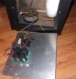
Mounting the 400VA trafo (below). AC send from the soft-start and return
to the bridge / capacitors will be the only "tether" to the enclosure.
(besides the speaker feed)....
After observing the "logitech way" , gluing the euro-terminal and a few other
choice objects could not hurt.
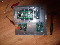
My only remaining concerns are the relays (in the micro-phonics department).
I might integrate the plate neoprene seal with some strategically placed foam
neoprene around the relays and caps. Fast-ons , trafo's and bridges are
pretty much immune from the subwoofers onslaught.
Top - side (below 2) , with all the more vibration sensitive components,
should be alright.
Time to wire it up .🙂
OS
Mounting the 400VA trafo (below). AC send from the soft-start and return
to the bridge / capacitors will be the only "tether" to the enclosure.
(besides the speaker feed)....
After observing the "logitech way" , gluing the euro-terminal and a few other
choice objects could not hurt.
My only remaining concerns are the relays (in the micro-phonics department).
I might integrate the plate neoprene seal with some strategically placed foam
neoprene around the relays and caps. Fast-ons , trafo's and bridges are
pretty much immune from the subwoofers onslaught.
Top - side (below 2) , with all the more vibration sensitive components,
should be alright.
Time to wire it up .🙂
OS
Attachments
Should I bypass the cap multipliers for a sub amp with a Wolverine input?
Yup , as much rail as you can muster. The Wolverine is one of the higher
PSRR IPS's and does not benefit much from the multipliers.
OS
I've got some rubber isolator standoffs that might work under your relays. We use them to mount ECUs on blower motors. Like these. http://www.mcmaster.com/#rubber-isolators/=w54l0n
Last edited:
I've got some rubber isolator standoffs that might work under your relays. We use them to mount ECUs on blower motors.
That might make them vibrate more in one plane or the other. Covering them
with foam neoprene has quite the dampening effect.
I'll have to measure the rails from the outside ... or the control board might
even sense a short term disconnected rail/ac interrupt.
Only full tilt with intense movie bass would trigger this (if at all ??).
edit - I saw those on the link. That might damp VLF from a vehicle , but 50-100hz+
might be out of spec. ??
OS
Last edited:
Is the size of the electrolytics at the output devices critical? Can they be 100uF?
That's what I'm using. Keentoken said possible ringing <1u , but all is good
with 10u+ .... that includes 100u.
I have 2 pair 100u/100v in the empty OP space cap pads on my MT-200
setup.
Edit - I'm also using another 220u/100V right at my "cap multiplier free"
IPS V+ and V- terminals. You can jumper out some resistors to do this.
OS
Last edited:
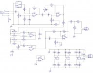
Where is the dc path for the + input of the chip U3.1 ? Does it work without one ?
What chip U3.1 ??
OS
Opamp U3.1 in the circuit in post #1.
I don't know how to post the diagram but here is the link.
http://www.diyaudio.com/forums/solid-state/269935-subwoofer-class-ab-plate-amp.html#post4227319
I don't know how to post the diagram but here is the link.
http://www.diyaudio.com/forums/solid-state/269935-subwoofer-class-ab-plate-amp.html#post4227319
Opamp U3.1 in the circuit in post #1.
I don't know how to post the diagram but here is the link.
http://www.diyaudio.com/forums/solid-state/269935-subwoofer-class-ab-plate-amp.html#post4227319
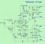
O ... K ! Jeff's EQ.
U3.1 is just an AC coupled inverting follower. As far as a DC path ,
Why would we want one on a subwoofer ?Maybe to see phono rumble ?
Some audiophiles suggest that a coupling cap in the audio path might degrade
SQ , hence the "DC" approach ....
But , for a sub .... <10hz can exceed Xmax quite easily - to be avoided.
A HP rolloff at 5-10Hz is good and besides , the main amp rolls off at <5hz
anyways.
Edit - u3.1 is the "rumble filter" (<5hz)
Hopefully , this explains the circuit/concept.
OS
Last edited:
You miss the point. Both opamps inputs ( +/- ) need to have a dc path otherwise the dc bias current has no path. All other inputs are accounted for except this one.
So the + input has to have a resistor to ground. As large a value as the bias current permits. Maybe 100K in this case !
So the + input has to have a resistor to ground. As large a value as the bias current permits. Maybe 100K in this case !
You miss the point. Both opamps inputs ( +/- ) need to have a dc path otherwise the dc bias current has no path. All other inputs are accounted for except this one.
So the + input has to have a resistor to ground. As large a value as the bias current permits. Maybe 100K in this case !
There is a phase pot missing in that schematic. I just never got around to posting updated drawings.
Attachments
There is a phase pot missing in that schematic. I just never got around to posting updated drawings.
So there I described it wrong while very sleepy 😱😱.
U3.1 mixes out of phase/in phase to get shift.
I actually was thinking of this.... This phase works , but creates shift that changes
phase with Fc. This is acceptable - but not perfect.
Short of a sophisticated multi-stage phase shifter , some digital DSP's offer
filtered phase shifters that can be set to "shift" just one band (<100hz).
Here you get perfect phase from 20-100hz - digital DSP.
Most 2.1 DAC's will sum L/R , and pass through a LPF for the sub output.
But , another analog filter will add phase shift. 🙁
The only perfect solution I've seen is a parasound 2.1 amp that has 3
separate DAC's.
OS
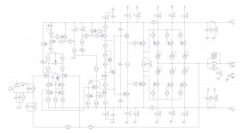
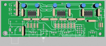
Does it look like I missed anything important? I notice R25 and C8 are missing from the input schematic. Are they not needed? The outputs will be MT200s. I need to draw a pattern for them yet.
No C8 , don't need that 3ppm at 20K. Sub will never see it, 😀
Just C9 / 100pF will give 5ppm LF (20-200hz).
I made R23 120R , omitted Q14 , R30,R31 .... added a diode across C9 (clamp)
with anode from Q12 base. R27 can be 47-68R ... 56R is cool.(I have 68R).
Runs at 5.3ma VAS I with a clamped overload.
You have everything else right on. 🙂
PS- this is my presently working sub amp - NOT a sim.
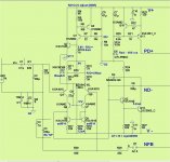
Edit - schema is better ... (below)
Edit 2 - my input filter is set lower C2=390pF
Attachments
Last edited:
I'll touch up the schematic and start laying out then. I also need clamping diodes(?) on the output and rails. I need to draw a pattern for them yet too.
I'll touch up the schematic and start laying out then. I also need clamping diodes(?) on the output and rails. I need to draw a pattern for them yet too.
Those are not "clamping diodes" on the OPS. One set is for EMF (like on relay coils).
The other ones Andy T suggested to protect OP's from reverse Vce.
You are not using Jkeutmann's gerbers for the OPS ?
OS
- Status
- Not open for further replies.
- Home
- Amplifiers
- Solid State
- Subwoofer Class AB plate amp