The filters appear to "stack" and are combined when you generate the filter.
Okey okey - but how does it sound ? 🙂 🙂
//
Okey okey - but how does it sound ? 🙂 🙂
//
Different 😉
The tonal balance seems a bit more even. I think it's less "shouty" and more smooth.
But it's easy enough to load the filters, so have a listen.
I will!
Sören, there was a question about oversampling in the DAC. Would you care to comment on this please?
//
Sören, there was a question about oversampling in the DAC. Would you care to comment on this please?
//
A processing stage model of the DAC and where the filters are entered would be educational.
//
//
Hi Søren. I'm working on ideas for a stackable plug-in board for the DAC and I see the HiFiduino article includes a mechanical drawing of the board mounting, output socketry etc. Would it be possible to provide additional information to detail the positions of J1, J2 and J3?
Many thanks.
Ray
Many thanks.
Ray
Why not upsample thus avoiding any filter? Can that be done on the FPGA?
Are you talking about non oversampling mode ? That can easily be done, t.ex. for 44.1:
Enter 8x 1.00000 as filter coefficients, 8 taps and gain set to 1.
The 8 is for 8 times oversampling, use 4 and 2 for other oversampling rates,
just like the 352/384 bypass filters using 1.
Again, I don't recommend non oversampling, and you then need the compensating filter for the 3db loss at 20 khz.
A processing stage model of the DAC and where the filters are entered would be educational.
//
I'm not sure what you're asking about her, the filters are described in post # 1285:
http://www.diyaudio.com/forums/vend...magnitude-24-bit-384-khz-129.html#post4212417
I have posted an updated design of my amanero input board to the implementation thread, post #399.
I think your board serves a different purpose, it is smaller and simpler. Some people may prefer that, don't abandon it!
For my configuration with the Edel_NMR I need just the 3 U.FL. connectors and the external 3,3V that I already have.
So, I think that is not more sense for me to go ahead with the design of the board. I don't have any interest to run a GB if cannot help the community.
I think your board serves a different purpose, it is smaller and simpler. Some people may prefer that, don't abandon it!
Hi Søren. I'm working on ideas for a stackable plug-in board for the DAC and I see the HiFiduino article includes a mechanical drawing of the board mounting, output socketry etc. Would it be possible to provide additional information to detail the positions of J1, J2 and J3?
Many thanks.
Ray
I second that, including the position of J7 and mounting holes as well.
I've attached a .skr with the 44.1 filter replaced with a minimum phase filter, linkwitz riley "shape" and 12dB filter slope and corner frequency of 159994.8Hz. My numbers are probably off but I'm setting the corner frequency at 0.4535*fs where the fs is 44100 * 8. (I re-read POS's post and corrected from 384 -> 352.8, oops)
I'm not sure why, but the rePhase filter is about 6dB quieter than the one Søren made, so
cheers
Paul
A -3db at .4535 output sample rate is almost like no filtering. Any filtering work should be done relative to the input sample rate....
Don't know why the filter is off 6 db, maybe the design of rePhase need to be checked.... Anyway, you can add the needed gain in the 1021filt.txt file, using the "multiplier" parameter.
I'm very interested in hearing the result of experimenting with filters, but it should be real filters, like if using the L-R filter slopes it should be more like 192+ db/octave slopes....
Are you talking about non oversampling mode ? That can easily be done, t.ex. for 44.1:
Enter 8x 1.00000 as filter coefficients, 8 taps and gain set to 1.
The 8 is for 8 times oversampling, use 4 and 2 for other oversampling rates,
just like the 352/384 bypass filters using 1.
Again, I don't recommend non oversampling, and you then need the compensating filter for the 3db loss at 20 khz.
Is there a way to enable / disable filters by serial commands? Would something like that even make sense?
And while we are on the subject (of serial commands), are there any undocumented serial commands that we should know of? For example, is there a way to get feedback on the state of the FIFO (perhaps like % full or something?) or any of the inner workings of the uC / FPGA?
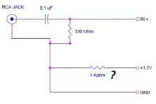
Soren!
Do I need the 1Kohm resistor????
That schematic is incorrect.
Is there a way to enable / disable filters by serial commands? Would something like that even make sense?
And while we are on the subject (of serial commands), are there any undocumented serial commands that we should know of? For example, is there a way to get feedback on the state of the FIFO (perhaps like % full or something?) or any of the inner workings of the uC / FPGA?
Sorry, I will only document what needed for normal use....
A -3db at .4535 output sample rate is almost like no filtering. Any filtering work should be done relative to the input sample rate....
Don't know why the filter is off 6 db, maybe the design of rePhase need to be checked.... Anyway, you can add the needed gain in the 1021filt.txt file, using the "multiplier" parameter.
I'm very interested in hearing the result of experimenting with filters, but it should be real filters, like if using the L-R filter slopes it should be more like 192+ db/octave slopes....
So should I generate filters at 44100 rather than 352800 as POS suggested?
Sorry, I will only document what needed for normal use....
Fair enough. 🙂
When testing we do a FFT and measure distortion at -1db, we don't really see any difference between the different version as the initial precision is so good, even on less precise resistors.
But I expect long term the boards with more precise resistors will change less than the less precise resistors as temperature and long term drift are significant better with the more precise resistors....
Thanks Søren.
Were you able to hear any difference in sound between the versions with 0.05% and 0.01% resistors?
So should I generate filters at 44100 rather than 352800 as POS suggested?
No, sample rate should be set at 352800, the rate it runs at. But filter parameters should be set for what you want it to do, those two things in principle don't have anything to do with each other.
Thanks Søren.
Were you able to hear any difference in sound between the versions with 0.05% and 0.01% resistors?
Haven't tried, but as I have stated before, I doubt there are any audible difference, at least not short term.
- Home
- Vendor's Bazaar
- Reference DAC Module - Discrete R-2R Sign Magnitude 24 bit 384 KHz