I like the way you handled the "R" of the CRC PSU. Nice way to rid yourself of the heat! Beware those open slots on the top for the MOSFEET heat escape though. Chance is a bugger and somehow, something will fall into your amp!
Hello,
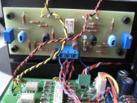
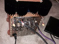
the boards are from the German AAA-Forum.
I´m always confused about the versions.
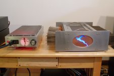
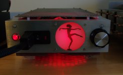
I guess it´s a V3 but with 24V rails (2 x 18V 1000VA Transformers 🙂
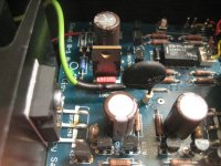
The transistors are FQA12P20/FQA16N25.
The temterature of the heatsinks is aprox 55°C .
The V-meter is mesauring the Bias at one resistor 600mV is 1,2 A Bias.
But it´s an optical gimmick ...
For this amp I was to lazy zu install a perforated plates at the open slots 😉
Kind regards
Andreas
the boards are from the German AAA-Forum.
I´m always confused about the versions.
I guess it´s a V3 but with 24V rails (2 x 18V 1000VA Transformers 🙂
The transistors are FQA12P20/FQA16N25.
The temterature of the heatsinks is aprox 55°C .
The V-meter is mesauring the Bias at one resistor 600mV is 1,2 A Bias.
But it´s an optical gimmick ...
For this amp I was to lazy zu install a perforated plates at the open slots 😉
Kind regards
Andreas
F4 gets it's mate
It is so very cool that Nelson Pass has not only given us all these super designs to build and helps us build them he has made them to work so well with each other!
I know what I have now is basically a BA3/complentary with the addition of a BA3 as preamp to the F4 but I didn't know at all when I started building what I'd be building or needing. It is real happiness to have this pairing available; a match no one should ever split asunder.
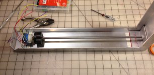
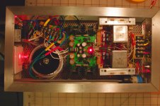
The last two pictures may be of some service to other builders showing how I used a 16" spade bit into a regular knob - it serves well as an extension. And the finalized trapeze for the oversized oil caps incorporating access to the resistors needed for biasing.
Not only was it a fun build but the pairing is really magic, a perfect marriage
It is so very cool that Nelson Pass has not only given us all these super designs to build and helps us build them he has made them to work so well with each other!
I know what I have now is basically a BA3/complentary with the addition of a BA3 as preamp to the F4 but I didn't know at all when I started building what I'd be building or needing. It is real happiness to have this pairing available; a match no one should ever split asunder.
The last two pictures may be of some service to other builders showing how I used a 16" spade bit into a regular knob - it serves well as an extension. And the finalized trapeze for the oversized oil caps incorporating access to the resistors needed for biasing.
Not only was it a fun build but the pairing is really magic, a perfect marriage
Attachments
-
 BA3 and F4 front.jpg614.9 KB · Views: 2,033
 -
 BA3 unit for installation web.jpg845.2 KB · Views: 878
 -
 stepped attenuator with extension.jpg510.8 KB · Views: 1,767
 -
 BA3 power up Web.jpg964.5 KB · Views: 1,866
 -
 BA3 pre dancer close.jpg556.4 KB · Views: 1,919
 -
 ba3 and F4 overhead.jpg342.1 KB · Views: 1,940

Wow! …one of the most beautiful aesthetic synergies I've seen between the wood and the metal....absolutely gorgeous. I bet it doesn't sound bad either😉
Mario
Mario
Nice 🙂 is it backlighted frosted plexi on the front panels?
Yes.
Thanks ZM!
😱
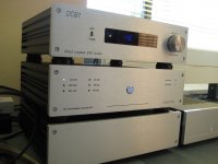
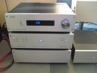
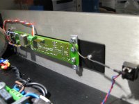
Finally ready, my take on a DCB1- preamp- stepped volume control with remote and input selector. I can control my DCB1 from the couch, now I'm happy...😀
I don't know if it belongs to the Pass sector, but it's based on a B1 so....
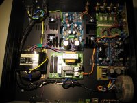
It's a (hot rodded 200mA) Mesmerize DCB1, with cut off volume and relay section. A Relaixed Passive, relays controlled attenuator, a Super Regulator, and a Juma BAF 2013 preamp and also some PCB's I made myself. With my old etching stuff from the 80's 🙂
It sounds wonderful, I can switch in an additional 12 dB gain when I need to have more power. ( For my VFET CSX1's for example)
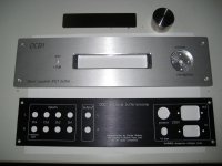
The frontpanel and backpanel are designed with frontpanel express.
Thanks to: Nelson Pass, Jos van Eijndhoven, Salas, Walt Jung, Jan Didden, Juma and the DIYaudio community 😀
Walter
I don't know if it belongs to the Pass sector, but it's based on a B1 so....
It's a (hot rodded 200mA) Mesmerize DCB1, with cut off volume and relay section. A Relaixed Passive, relays controlled attenuator, a Super Regulator, and a Juma BAF 2013 preamp and also some PCB's I made myself. With my old etching stuff from the 80's 🙂
It sounds wonderful, I can switch in an additional 12 dB gain when I need to have more power. ( For my VFET CSX1's for example)
The frontpanel and backpanel are designed with frontpanel express.
Thanks to: Nelson Pass, Jos van Eijndhoven, Salas, Walt Jung, Jan Didden, Juma and the DIYaudio community 😀
Walter
Attachments
-
 DCB1_10.JPG247 KB · Views: 801
 -
 DCB1_9.JPG259.3 KB · Views: 880
 -
 DCB1_8.JPG257.3 KB · Views: 929
 -
 DCB1_7.JPG521.6 KB · Views: 692
 -
 DCB1-6.JPG466.2 KB · Views: 748
 -
 DCB1_5.JPG501.2 KB · Views: 1,755
 -
 DCB1_4.JPG491.1 KB · Views: 1,813
 -
 DCB1_3.JPG272.7 KB · Views: 1,870
 -
 DCB1_2.JPG416.1 KB · Views: 1,933
 -
 DCB1_1.JPG274.6 KB · Views: 1,994

Pass DIY Addict
Joined 2000
Paid Member
Awesome job, Walter! I love the clean and matched appearance of your system. Can you provide a little more detail about that +12dB switch? I'm looking at an MV04 kit from ebay to add remote control to my DCB1 build. So many ideas, so little time...
John: Wow! Very nice pairing and interesting visual aesthetics on the BA-3 and F4 pair! Whose oil caps did you use? I have a BA-3 that is almost done (I used Obbligato Gold caps) and an F4 that works, both need a chassis now. I'm trying to decide whether to just join the two, or try to "cleave off" the first part of the F4 and hard wire the BA-3 directly in to reduce the number of JFets and other parts in the signal path.
Eric
Last edited:
eric - MGBP oilers from kwtubes on epay.
Keeping them separate will isolate the power supplies and allow for you using each for different service in the future. There is no end to this building stuff 😀
Keeping them separate will isolate the power supplies and allow for you using each for different service in the future. There is no end to this building stuff 😀
Thanks everybody!
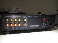
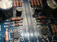
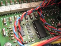
@Eric: with the switch on the frontpanel I switch a little high quality audio relay mounted on the PCB I made myself. See picture, the schematic is from Juma.
I removed the input pot and the input capacitor to keep it DC coupled, also instead of the 7812 and 7912 regulators I used the Superregulator boards from the store at + and - 15V. I also played with R8 and R9 to get more gain.
Walter
Attachments

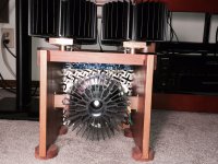
My F5 build
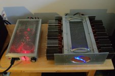
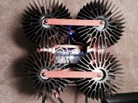
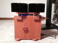
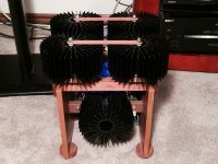
Here's my F5 mono blocks, started in 2011, finished in 2015. I wanted to isolate the outputs so I could mount the mosfets directly to the copper spreader bar. I lapped and polished the bottom of the heatsinks, spreader bar and where the mosfets were mounted on the spreader. The mosfets and heatsinks were mounted using 24k diamond paste and the heatsinks are attached to the spreader using valve springs under compression.
Here's my F5 mono blocks, started in 2011, finished in 2015. I wanted to isolate the outputs so I could mount the mosfets directly to the copper spreader bar. I lapped and polished the bottom of the heatsinks, spreader bar and where the mosfets were mounted on the spreader. The mosfets and heatsinks were mounted using 24k diamond paste and the heatsinks are attached to the spreader using valve springs under compression.
Attachments

Here's my F5 mono blocks, started in 2011, finished in 2015. I wanted to isolate the outputs so I could mount the mosfets directly to the copper spreader bar. I lapped and polished the bottom of the heatsinks, spreader bar and where the mosfets were mounted on the spreader. The mosfets and heatsinks were mounted using 24k diamond paste and the heatsinks are attached to the spreader using valve springs under compression.
You've taken great care to shed the heat and I applaud the unconventional format! Bravo!

I'm a woodwoker coming to this building of things metal. I miss the warmth of wood objects in my room. Yet, one woodworker to another, try some angle aluminum for reinforcement if nothing else. Woodworking tools work fine on T5 & T6 series aluminum 🙂 with it you can get even better. 😉
Happy listening and congratulations on a successful build! 😀
- Home
- Amplifiers
- Pass Labs
- Pictures of your diy Pass amplifier