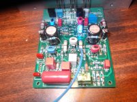
My 2mHZ oscillation is back on a brand new pair of output boards. KSA1381/C3503 predrivers, 2SA1186/C2837 drivers, and 2SA1295/C3503 outputs. I've got cap multipliers on these boards. I'm going to try them out bypassed later today.
Same with other IPS's ??
Is your bias "squirrly" with the 2mhz ?
I have my OPS's remachined and am running them now to test stability. I'll
attach one of my Kypton C's to compare with yours (I/V readings). I can run at either 40 or 66V rails , as well.
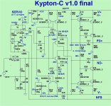
Edit .. what caps are at the kypton VAS (tan ones) ... they dont look like the 33p poly's I use
or silver mica's ???
OS
Last edited:
Bias isn't bad. The oscillation isn't there with CFA-XH. It's lower frequency and voltage with Symasui. I haven't had a chance to experiment much yet.
Neither have I.
If anything , the cap multiplier would make things better.
I've actually listened to the "C" (at a quite high volume).
I also might have oscillation , but I can't tell - it sounds great.
OK , just put those 2.4k's and trimmer in the "C" (below 1).
.... 63V rails
(below 2) - are my exact part values. Vas is 7.7ma on R22 minus 68V/33K for
R25 = 2.06ma for the blue leds .... a 5.64ma vas I.
Never adjusted the R24 -50K trimmer... should be 25K as new.
I'll see if the servo has anything to do with operation ( not in yet).
How big (amplitude) is this oscillation ?
Edit - try running G2 direct to PS ground and don't return your load ground to the OPS (right
to the PS. You mean the symasui oscillates , too ?
OS
Attachments
Last edited:
Board error !!!
Added my servo - did not work.
Edit - servo "railed" and could only get offset down to 40mv.
R6 on PCB was marked "10K" , I just stuffed it as marked.
Should be 220R , the mirrors were "floating" with just a high Z
servo reference. Put the 220R in .... 2mv steady offset.
Don't know if this could cause oscillation , but it caused me some
"head scratching" 😕 .
Jeff , review my last posted schema - and double check everything !
Mine seems to be quite solid now , normally offset is also "squirrly"
with oscillation .
A very slow cycle between 1.8- 2.1mv - pretty steady. 🙂
Edit - with servo Z so high ... parasitic feedback through R8 from the
G1-G2 current returns could be an issue. R8 is a safety thing - it can actually be
removed. C9 could of been the only thing keeping this thing from
getting full blown FB though the grounds.
OS
Last edited:
I've been planning to test my KryptonC but have been struggling with a couple other amps. I'm glad you guys beat me to it. I will benefit from your trials. So glad you finally have a test circuit OS.
Blessings, Terry
Blessings, Terry
I did notice the ground was dirty but never got to running it directly to the star ground. I can't remember for sure but I think the oscillation was around 1.5V. The oscillation on Symasui was around 1 volt. These are the boards that were modified to make the servo settle faster. They didn't seem as stable after the changes.Board error !!!
Added my servo - did not work.
Edit - servo "railed" and could only get offset down to 40mv.
R6 on PCB was marked "10K" , I just stuffed it as marked.
Should be 220R , the mirrors were "floating" with just a high Z
servo reference. Put the 220R in .... 2mv steady offset.
Don't know if this could cause oscillation , but it caused me some
"head scratching" 😕 .
Jeff , review my last posted schema - and double check everything !
Mine seems to be quite solid now , normally offset is also "squirrly"
with oscillation .
A very slow cycle between 1.8- 2.1mv - pretty steady. 🙂
Edit - with servo Z so high ... parasitic feedback through R8 from the
G1-G2 current returns could be an issue. R8 is a safety thing - it can actually be
removed. C9 could of been the only thing keeping this thing from
getting full blown FB though the grounds.
OS
I see changes to R6, R15, R16, R22, R23, R26 and R27. Did I miss anything? My servo seemed to be working as it was but I'll make all these changes anyway. That's a huge change on R6.
I've attached the schematic these were drawn from.
Attachments
Board error !!!
Added my servo - did not work.
Edit - servo "railed" and could only get offset down to 40mv.
R6 on PCB was marked "10K" , I just stuffed it as marked.
Should be 220R , the mirrors were "floating" with just a high Z
servo reference. Put the 220R in .... 2mv steady offset.
Don't know if this could cause oscillation , but it caused me some
"head scratching" 😕 .
Jeff , review my last posted schema - and double check everything !
Mine seems to be quite solid now , normally offset is also "squirrly"
with oscillation .
A very slow cycle between 1.8- 2.1mv - pretty steady. 🙂
Edit - with servo Z so high ... parasitic feedback through R8 from the
G1-G2 current returns could be an issue. R8 is a safety thing - it can actually be
removed. C9 could of been the only thing keeping this thing from
getting full blown FB though the grounds.
OS
Hi
I saw in a earlier post in this thread that Kypton C schematic where the "Feedback resistor" R15,R16" are 1Kohm and R14,R15 are 39ohm
for low distortion
Did anybody test that and is it safe and stable?
My R15 and R16 are 1K right now and my board is unstable.
Can you please try 2k2 and 68R instead?
Can you please try 2k2 and 68R instead?
I've got 68R and 2k4 in right now. I've got to sort out the VAS issue.
I've made the changes to one board. Now my VAS current is double what it should be.
The VAS should be high @ 8ma because it is the main Re's I (R22/27) minus
the LED current that determines the actual VAS I.
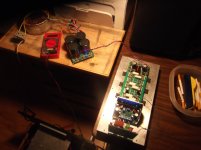
I left mine on overnight (below) - still 527mv -R22 (7.75ma) - 2.3ma LED I.
Offset after cleaning flux from TL072 is .6mV.
I notice LED's pass more current as total VAS current increased with temp. , keeping
the VAS at a constant current. Cool to see this in real life.
This IPS is now 5.4ma VAS , Ill swap it with my wolverine - which is also a
solid 5.4ma .... to see if there is any change to the OPS.
PS - on this test amp (and my dedicated amps) Load returns all go directly
to the chassis star (or cap bank ground) , not the OPS G1.
I'm in the "trenches" with Y'all now .. huh ? 😀Still4given -I've been planning to test my KryptonC but have been struggling with a couple other amps. I'm glad you guys beat me to it. I will benefit from your trials. So glad you finally have a test circuit OS.
Edit - that toroid fell off the end of the board and fell right on my big toe !! (in the trenches - pain for amps).
OS
Attachments
Last edited:
What should the voltage drop be across a blue LED? There seems to be a fairly wide range now. Maybe that's where some of my issues are starting.
Just broke off R8 on the PCB - offset is 0 ? wow !
Now , no path for any ground contamination to the mirrors.
No R8 , total current of R7/9 set the input pair I ... servo is
in total control now. If the servo failed (railed) , the OPS might
put out some hefty DC (but we have protection).
But , How often does a servo fail ?
OS
Now , no path for any ground contamination to the mirrors.
No R8 , total current of R7/9 set the input pair I ... servo is
in total control now. If the servo failed (railed) , the OPS might
put out some hefty DC (but we have protection).
But , How often does a servo fail ?
OS
What should the voltage drop be across a blue LED? There seems to be a fairly wide range now. Maybe that's where some of my issues are starting.
I just measured my blues (ones you ordered-kingsbright). 2.67V Vf.
This stays quite steady , unless you subject to 0-40C temperature swings.
If they light up the same they should drop the same Vf. As they heat the Vf
should drop a little ... (2.5+ - 2.6) , and current through R25/33K should increase.
R25 Voltage went from 68- <70V as I closed the front door to let this IPS
get warmer.
On this and any of the 5-6ma VAS's ... you do not need any heatsink.
They still run cool , even when I was running in my toasty amp case.
I DID add a very small piece of flashing cut with scissors to all the IPS's ,
just in case.
This is fun 😎 . (when things work , that is).
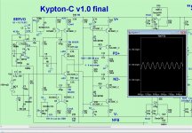
Simulator shows 84mv offset with no servo - that's what I had (86mv)
and nanovolt offset without R8 - this is what I have now.
Simulator matches the real deal almost exactly !!
OS
Should we follow AndrewT's advice and swap all the decoupling caps for ceramics?
I wouldn't bother swapping but I'd sure get some 1206 100nF/100V X7R SMD caps and solder them in parallel on the opposite side. I use them exclusively in all my PCB designs. They are cheaper than dirt too, less than 2c a piece.
Should we follow AndrewT's advice and swap all the decoupling caps for ceramics?
I'm using those red wima .1uf's and those "no-name" blue's you sent me ...
I notice no issues ??? This would not cause oscillation ?
OS
- Home
- Amplifiers
- Solid State
- Slewmaster - CFA vs. VFA "Rumble"