They carry DC current only in that the current drawn on th rails is either positive or negative. The currents are highly time varying though and therefore couple easily into receiving circuits.
Only a small proportion of the current flows from + to - rail - this is the quiescent current in a class AB amplifier. By far the majority of the current is flowing from either one of the power rails through the load and then to ground.
Only a small proportion of the current flows from + to - rail - this is the quiescent current in a class AB amplifier. By far the majority of the current is flowing from either one of the power rails through the load and then to ground.
Last edited:
The problem with adding AC is that the rails don't carry an alternating current but a DC current.
but that is exactly the point......
however, there is a small dc current flow from rail to rail, it is called idle dc current bias....
ac voltage is developed as output ac voltage from the output node, into the load and then back to the psu ground..
Can someone tell me briefly why there appears to be two large electo's connected between the output transistor emitters, and the rails?The only thing I cans say is look at a D. Self design and see for yourself that he does not actually use the above layout.
The Signal Transfer Company: Trimodal Power Amplifier

Last edited:
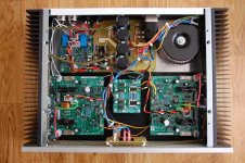
The long trace running through the middle of the board is the power/output/decoupling ground. The two traces connected to the output transistor emitters are the positive and negative rails and each rail has a 220 uF and a 100 nF capacitor to the ground trace.
Um, but isn't this an emitter-follower output (i.e. collectors connected to the rails)?The two traces connected to the output transistor emitters are the positive and negative rails and each rail has a 220 uF and a 100 nF capacitor to the ground trace.
It has been explained several times, the currents don't return via the opposite rail.
What you have to realise, Mark, is I'm the one doing the explaining here.
Look at this diagram of a CE amplifier. How do you calculate the input impedance?
The input impedance is calculated as RB1 || RB2 || hfe(RE+re) from memory.
An externally hosted image should be here but it was not working when we last tested it.
Why is RB1 taken as being in parallel with RB2? Look it up in Horowitz and Hill. It's because the positive rail is at AC ground.
You guys need to revisit your basics, you don't really know how to analyse a circuit in AC vs. DC terms.
In post 350 I showed the positive and negative rail currents. I have also posted links that show how D. Self lays out his amps. Others have also tried to explain why the rails and ground should be twisted.
That is a simplification (albiet a useful one for many things), The power rail (And in fact also the ground) is in fact a rather complex mess of an RLC network which couples to various other things via other RLC networks.It's because the positive rail is at AC ground.
It just so happens that at low frequency and when the currents are small you can approximate the lines themselves as simple conductors and the bypassing as zero impedance.
These assumptions however break down as you move away from DC and as either the load impedance drops or you try for distortion figures dominated by the common impedances.
Part of the skill is in knowing when the simplifying assumptions work and when you actually need to think about what is really happening rather then an idealised model.
Regards, Dan.
The circuit you showed has a single rail. It's rather different for a bipolar rail circuit such as a conventional transistor amp. You need to appreciate the difference between the paths taken by the idle current and the load current. I have drawn them for you:What you have to realise, Mark, is I'm the one doing the explaining here.
Look at this diagram of a CE amplifier.
Attachments

Last edited:
The problem with adding AC is that the rails don't carry an alternating current but a DC current.
your postings are confusing readers, you talk of currents without making distinctions as to whether the current is dc or ac....
It's rather different for a bipolar rail circuit such as a conventional transistor amp. You need to appreciate the difference between the paths taken by the idle current and the load current. I have drawn them for you:
The main twisted triplet inside of the chassis from the amplifier PCB to PSU would be the plus/minus rails and the speaker's ground return? Would you then close couple the signal grounds coming in from source and any other decoupling grounds on the amp PCB to that triplet?
That is a simplification (albiet a useful one for many things)
Thankyou. It's good enough in this case.
It's like pulling teeth.
The circuit you showed has a single rail. It's rather different for a bipolar rail circuit such as a conventional transistor amp. You need to appreciate the difference between the paths taken by the idle current and the load current. I have drawn them for you:
Read my posts. I already explained why we ignore the loop currents associated with the load return and the supply rails and attach the load return to a spur at the midpoint between the supply caps.
You do recognise this description 'attach the load return to a spur at the midpoint between the supply caps'? This is only what virtually every piece of grounding advice extant recommends.
Look at the diagram I posted.
Except that it isn't, not really.Thankyou. It's good enough in this case.
5534, well yea, you will probably get away with it, but with the modern fashion for ever more GBP it becomes seriously problematic when the target is something like a mixer channel strip or such with many opamps.
In power amps (Where the speaker return is often to the middle of the filter caps as you say), the correct answer is to twist the two power lines AND the speaker output line together making a threesome back to the filter caps, then continue the speaker line to the speaker connectors twisted with the speaker return conductor.
The loop in this case is power line (whichever one is appropriate) -> speaker output -> bulk cap -> power line.
Any discussion of a loop issue can always be assumed to be talking about the AC component of the current.
Seriously, a copy of "Electromagnetic compatibility Engineering" is worth the time as it demistifies much in this area.
OK, so we've gone from 'never under the sun', to...
That's what I'm talking about, what is necessary what is not necessarily necessary.
As far as demystification is concerned, how 'bout next time starting out agreeing with me, and pointing out the cases where you think there might be exceptions, rather than me having to force grudging admissions?
We had a bunch of people here acting in blind ignorance of the fact that these currents can couple from rail to rail, and instead of helping me to disabuse them you start to raise objections with barely a nod to the truth of what I was saying.
And I'm pretty sure you're exaggerating.
...well yea, you will probably get away with it...
That's what I'm talking about, what is necessary what is not necessarily necessary.
As far as demystification is concerned, how 'bout next time starting out agreeing with me, and pointing out the cases where you think there might be exceptions, rather than me having to force grudging admissions?
We had a bunch of people here acting in blind ignorance of the fact that these currents can couple from rail to rail, and instead of helping me to disabuse them you start to raise objections with barely a nod to the truth of what I was saying.
And I'm pretty sure you're exaggerating.
In power amps (Where the speaker return is often to the middle of the filter caps as you say), the correct answer is to twist the two power lines AND the speaker output line together making a threesome back to the filter caps, then continue the speaker line to the speaker connectors twisted with the speaker return conductor.
This is bassackwards BTW, you've got line and return swapped.
Read my posts. I already explained why we ignore the loop currents associated with the load return and the supply rails and attach the load return to a spur at the midpoint between the supply caps.
You do recognise this description 'attach the load return to a spur at the midpoint between the supply caps'? This is only what virtually every piece of grounding advice extant recommends.
Look at the diagram I posted.
The point I am trying to make is that D. Self connects the load returns (output ground) to the decoupling (local) ground of each amp board. He does not connect them to a spur at the midpoint between the supply caps. Other designers are doing the same.
No spur. No load return connected to PSU. Only twisted +/- rails and ground between amp and PSU.
Attachments
Last edited:

- Status
- Not open for further replies.
- Home
- Source & Line
- Analog Line Level
- Comment on Grounding Scheme?