Please read my website about my thoughts on paralleling chips and jitter ....
dddac Website jitter and parallel chips
dddac Website jitter and parallel chips
Please read my website about my thoughts on paralleling chips and jitter ....
dddac Website jitter and parallel chips
Ah, interesting link, which probably makes sense! I tried to verify this by trying to measure the effects of multiple boards on jitter as I do have this 10ns jitter due to the synchronous reclocking via Acko's reclocking module. (I have a 4-deck setup).
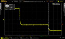
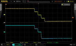
For the test setup, I am simply measuring the output after the I/V resistors when playing a 1kHz square wave at 44.1 kHz/16bit. Interestingly, the 10ns jitter propagates right to the output of the DAC as can be seen in the following picture (right channel):
For comparison, I measured the left channel - and uh, oh, look at the square wave: 😱
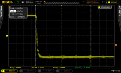
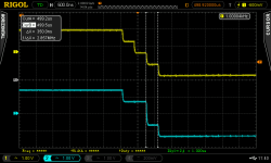
One can easily see the 10ns jitter but there's a stairstep after 722ns there that is absent on the right channel which can be seen here:
The rising edge on the left channel has a similar pattern:
Hmmm, as the stair-step is approx 1/4 of the full signal height it seems that one of the decks has some strange error. 🙁 Oh my, I should not have brought up this theory of a broken deck that distorts the signal and is "overruled" by adding other decks. It's like a self-fulfilling prophecy...
Well, before disassembling my 4-deck stack, I wanted to know if anyone has a clue what this could be / why this would happen? What's furthermore interesting is that I measured the signal also between "ground - negative" and "ground - positive" on the left channel, with the same results.
I find it also very interesting that the faulty deck is obviously not fully broken but the signal output seems to be delayed for ~ 700ns. Perhaps there's some capacitor broken or not soldered well?
Any help is appreciated!
Best Regards,
Hermann
P.S.: At least, when disassembling my stack I'll be able to report jitter for a one-deck, a 2-deck and 4-deck combination...
Attachments


How strange Hermann, but how nice to be able to see the problem clearly. I wonder if you should check your resistors on you dac boards. Each channel has a group of 3 resistors and the middle one's job is to delay the audio signal by a specific amount. If you have a blue mainboard I think they should all be 100r or 1k for the Red main board. That would be my guess.
How strange Hermann, but how nice to be able to see the problem clearly. I wonder if you should check your resistors on you dac boards. Each channel has a group of 3 resistors and the middle one's job is to delay the audio signal by a specific amount. If you have a blue mainboard I think they should all be 100r or 1k for the Red main board. That would be my guess.
Thanks for your quick reply!
Hmmm, just had a look at the decks & schematics of the DAC decks - yes, I can see 3* 100 Ohm resistors, but they are between the I2S signals and the PCM1794A - how would a resistor delay the signal? (Don't get it).
Best Regards,
Hermann
by the value of R and the capacitive Input of the port...
I do not think this is the issue though. also still not sure how you measure this. re my comment on the earth of the scope at the hot side of the DAC ?
I do not think this is the issue though. also still not sure how you measure this. re my comment on the earth of the scope at the hot side of the DAC ?
Ah, interesting link, which probably makes sense! I tried to verify this by trying to measure the effects of multiple boards on jitter as I do have this 10ns jitter due to the synchronous reclocking via Acko's reclocking module. (I have a 4-deck setup).
Well, while just reading the TI PCM1794 and cannot find any information on which clock edge the I/V data gets loaded. While this has to be done in sync with L&R channel! In the older days PCM63 data sheet was very clear as the PCM1704...
Just a simple guess on the negative edge on LRCK/WDCK with the t(dh) hold time... but here is a combo of Sigma delta & ICOB decoder at work.
Also simple D-Jitter measurements would show, whats about..
Hp
Just come back to this thread after a few months, 373 pages ! --> it becomes difficult to find a specific info ...
I would just like to know if the new 1794S mainboard provides a "better sound" than the 1794 (for the same number of DAC modules) when used with the SPDIF input, because the front SPDIF / I2S conversion card (1543mk2) is no longer needed , the TentLabs clock is supposed to be more accurate, etc... ?
Have some of you already experimented the upgrade from the 1794 to the 1794S wusing SPDIF with the same number of DACs modules ?
Thanks very much !
I haven't used the spdif, but it's worth swapping to the new mainboard for the improved clock delay circuit if nothing elseJust come back to this thread after a few months, 373 pages ! --> it becomes difficult to find a specific info ...
I would just like to know if the new 1794S mainboard provides a "better sound" than the 1794 (for the same number of DAC modules) when used with the SPDIF input, because the front SPDIF / I2S conversion card (1543mk2) is no longer needed , the TentLabs clock is supposed to be more accurate, etc... ?
Have some of you already experimented the upgrade from the 1794 to the 1794S wusing SPDIF with the same number of DACs modules ?
Thanks very much !
by the value of R and the capacitive Input of the port...
I do not think this is the issue though. also still not sure how you measure this. re my comment on the earth of the scope at the hot side of the DAC ?
Many thanks for your input, I did single ended measurements as you recommended (for the FFT I did not get better results but I don't want to concentrate on this further as I fear that the FFT of my DSO is not precise enough (12 bit) to get decent results).
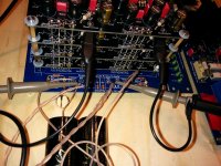
I investigated the problem further and it seems that no deck is broken, but the problem is somewhere in the digital domain. First of all my measurement setup:
At first I switched everything on - and surprise - no stairstep, all o.k. Only the 10ns jitter from the synchronous reclocking as expected:
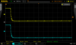
Interesting - I did not change anything since yesterday except maybe the placement of the probes. O.k., then I then replaced the S03 reclocker by the isolator to check jitter on this one, once again, a clean signal (with 2ns jitter) and I switched back to the S03 - and wow, the stairstep is back again 😱 :
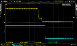
Hmmm, resetting the DDDAC (Power off/on) results in a different pattern:
One can see here that a stairstep has the length of BCK. Interesting. When I reset the RPi, or simply press "pause/play", the pattern changes again, sometimes the signal is clean on one channel:
However, I could not get back to the clean signal, I tried resetting everything once again, no chance. Replacing the reclocker to the isolator and back makes no difference, too. Hmmm, I can't figure out what I did initially so that the output was clean? Maybe some capacitance is building up in some way?
Hmmm, I did change the I2S cables during operation, perhaps this is not a good idea as something gets "unsychronized"? Nevertheless, this effect should go away, if I reset everything, right?
Anyway, the problem is quite likely in the digital domain, however, I have no clue how to solve this - any ideas?
Best Regards,
Hermann
Attachments
After the long delay of moving house, I finally came around to populating my 4 board DDDAC with the 2SK208 (“O”, type) JFETs based CCS’s, onto the mysteries pin 20.
This update has become quite lengthy, apologies for this. If anything, it’s like a recap for myselve as well…, this upgrade had been on my mind for a few to many months.
In the last 6 months or so a lot of collaboration took place in this thread to figure out what to do with pin 20 and later what CCS to use/build to put onto it. A few very reputable guests chipped in.., but mainly James, Carlsor, Enrico and Rick (I probably misted someone, appologies..), did most of the leg work, thanks guys! Eventhough, the discussion in this thread has moved on, I feel this was where this update belongs.
I can’t remember exactly who, but someone finally came up with using the (discontinued) 2SK246 and the 2SK208, it’s SOT-23 style replacement. Tolerances of the newer 2SK208 looked to be better, so I decided to go with them. Accoording to Carlsor and others both the “R”and “O” bin version would be suitable, so I bought a bunch of both.
One main concern for me about using a CCS had been how it’s value would vary due to the temperature inside a 4 board stack. The interior of my case heats up to 40Celcius. So I wanted to be sure the CCS’s would stay as constant as possible across the temperature band (20C-40C). In order to test this I heated up a the JFET’s with my hot air rework station while monitoring it’s temperature with an infrared temp sensor and it’s output current. In contrast to other CCS solution I’d tested this with before, the 2SK208 remained surprisingly stable. It shifted about 0.002mA (0.5% around 0.4mA), across the 20C-60C band, in contrast to for example the LM134, which varied about 10% which made it unsuitable, a considered candidate at some point.
I did do a few thing different in that, in contrast to others, I pre calibrated the CCS’s before installing them (on a little breadboard, with a potmeter) and I used a single “set”ting resistor once I knew it’s correct value per individual JFET. In the particular batches of 2SK208’s I received, the “O” versions where by far the most consistent. There were concerns raised that the final calibration could only be done in situ, but this didn't turm out to be a problem for me.
In the end I made 20 CCS’s based on these adapters:
From HK:
http://www.ebay.co.uk/itm/271302218170?_trksid=p2059210.m2749.l2649&ssPageName=STRK%3AMEBIDX%3AIT
From Germany:
http://www.ebay.co.uk/itm/151240428797?_trksid=p2059210.m2749.l2649&ssPageName=STRK%3AMEBIDX%3AIT
Like so:
I used an assortment of 1206 size SMD resistors to set the CCS’s
Out of the 20 adapters I put together I made a selection 8, of which 6 had turned out with a spread of 0.25% and 2 with a spread of 1%, around the 0.400mA.
On the side of caution I measured the dreaded DC off-set before I installed just two CCS”’s on the top board of my 4 board stack as test. After installation the DC offset hadn’t move a single mV and even with just one board modified I already perceived a noticeable difference in SQ. So I was good to go.
So yesterday I refitted the 4 boards with the CCS’s…, tested the DC-offset again, still no change. So pre calibration seemed to have worked a treat.
For a sense of size, sorry for the discusting looking board..
Obviously the update needs to burn in but first impression give a general sense of direction to where this is going.
In terms of sounds quality, this upgrade is a mayor improvement. The sound has become a lot more alive/fresh/expended. It’s like another veil has lifted more detail and timbre. In general this is a mayor improvement in SQ in my ears and improved the DDDAC in another big way. However I could imagine that it has become so “alive”/bright/edgy that this might not be to everybodies taste and could cause earlier listening fatigue. I suspect the burnin will smooth stuff out a bit. Also I perceive a more natural sound then before, so the brightness might actually need to be there.
I’m completely blown away by the fact that the DDDAC just keep giving, more and more. What a brilliant design that allows us to mess it up so badly. 😉
For those of you who are still sitting on the fence or reluctant to tear up your multiboard DAC (again), sorry for the good/bad news.
This update has become quite lengthy, apologies for this. If anything, it’s like a recap for myselve as well…, this upgrade had been on my mind for a few to many months.
In the last 6 months or so a lot of collaboration took place in this thread to figure out what to do with pin 20 and later what CCS to use/build to put onto it. A few very reputable guests chipped in.., but mainly James, Carlsor, Enrico and Rick (I probably misted someone, appologies..), did most of the leg work, thanks guys! Eventhough, the discussion in this thread has moved on, I feel this was where this update belongs.
I can’t remember exactly who, but someone finally came up with using the (discontinued) 2SK246 and the 2SK208, it’s SOT-23 style replacement. Tolerances of the newer 2SK208 looked to be better, so I decided to go with them. Accoording to Carlsor and others both the “R”and “O” bin version would be suitable, so I bought a bunch of both.
One main concern for me about using a CCS had been how it’s value would vary due to the temperature inside a 4 board stack. The interior of my case heats up to 40Celcius. So I wanted to be sure the CCS’s would stay as constant as possible across the temperature band (20C-40C). In order to test this I heated up a the JFET’s with my hot air rework station while monitoring it’s temperature with an infrared temp sensor and it’s output current. In contrast to other CCS solution I’d tested this with before, the 2SK208 remained surprisingly stable. It shifted about 0.002mA (0.5% around 0.4mA), across the 20C-60C band, in contrast to for example the LM134, which varied about 10% which made it unsuitable, a considered candidate at some point.
I did do a few thing different in that, in contrast to others, I pre calibrated the CCS’s before installing them (on a little breadboard, with a potmeter) and I used a single “set”ting resistor once I knew it’s correct value per individual JFET. In the particular batches of 2SK208’s I received, the “O” versions where by far the most consistent. There were concerns raised that the final calibration could only be done in situ, but this didn't turm out to be a problem for me.
In the end I made 20 CCS’s based on these adapters:
From HK:
http://www.ebay.co.uk/itm/271302218170?_trksid=p2059210.m2749.l2649&ssPageName=STRK%3AMEBIDX%3AIT
From Germany:
http://www.ebay.co.uk/itm/151240428797?_trksid=p2059210.m2749.l2649&ssPageName=STRK%3AMEBIDX%3AIT
Like so:
An externally hosted image should be here but it was not working when we last tested it.
I used an assortment of 1206 size SMD resistors to set the CCS’s
Out of the 20 adapters I put together I made a selection 8, of which 6 had turned out with a spread of 0.25% and 2 with a spread of 1%, around the 0.400mA.
On the side of caution I measured the dreaded DC off-set before I installed just two CCS”’s on the top board of my 4 board stack as test. After installation the DC offset hadn’t move a single mV and even with just one board modified I already perceived a noticeable difference in SQ. So I was good to go.
So yesterday I refitted the 4 boards with the CCS’s…, tested the DC-offset again, still no change. So pre calibration seemed to have worked a treat.
For a sense of size, sorry for the discusting looking board..
An externally hosted image should be here but it was not working when we last tested it.
Obviously the update needs to burn in but first impression give a general sense of direction to where this is going.
In terms of sounds quality, this upgrade is a mayor improvement. The sound has become a lot more alive/fresh/expended. It’s like another veil has lifted more detail and timbre. In general this is a mayor improvement in SQ in my ears and improved the DDDAC in another big way. However I could imagine that it has become so “alive”/bright/edgy that this might not be to everybodies taste and could cause earlier listening fatigue. I suspect the burnin will smooth stuff out a bit. Also I perceive a more natural sound then before, so the brightness might actually need to be there.
I’m completely blown away by the fact that the DDDAC just keep giving, more and more. What a brilliant design that allows us to mess it up so badly. 😉
For those of you who are still sitting on the fence or reluctant to tear up your multiboard DAC (again), sorry for the good/bad news.
Last edited:
I strongly recomend new dddac users to let this exellent sounding dac get some time to play in their setup before start different types of tweaking.
When I compare dddac against other dacs, there is one important difference, and that is the non fatigue sound signature. And this is a very important element in my world. It doesn't help how clean and detailed the sound is if you got tired of listening after a while.
System setup is also critical here. Since we all have different preferences there is no simple answer. A revealing setup will not enjoy a dac which is on the edge clear and to focused on details. A system not so revealing, will probably prefer it.
I am running dddac without caps and trafos on output and have changed the I/V resistors to shinkoh tantalum 2 watt and bigger transformers ( 250va ). That's all. And to be honest, the change in SQ going from stock transformers to ten times bigger, is very small, if any.
To verify this I must change back to stock trafos, but since the psu boards have been cut of this won't happen.
Hope all of you clever tweak guys not read this the wrong way. Some tweaking is ok, and often a smart thing to do, but it's important to reverse things after a while, and this is often hard to do after desoldering and cutting traces etc,,,, sometimes, when reverse tweaks, I have been surpriced as it turns out that it actually sounded better before.
Keep on tweak this great dac guys, but don't forget take a step back and reverse things when this is possible, just to be shure. And remember, it takes ofter longer time to evaluate SQ than you might think. Things that in first place sounds great, can over time tip over, and you are on the "tweak train" again.
Apologies if this information is hidden deep within this huge post but I can't seem to find it.
The DDDAC 1794S mainboard uses 3 regulators, 1 x LF50 and 2 x LF33.
Anyone know the current draw of the 3 individual regulators on the 1794S mainboard?
The DDDAC 1794S mainboard uses 3 regulators, 1 x LF50 and 2 x LF33.
Anyone know the current draw of the 3 individual regulators on the 1794S mainboard?
Last edited:
stijn001 CCS Upgrade Review
This is exactly how I would describe the change in sound from both the 2SK246Y and the 2SK208O CCS circuits. I listened carefully for how the sound could have been negatively impacted - but couldn't hear anything. After the 300 hours of burnin play time the musical flow became more relaxed but still with all the detail and liveliness. This upgrade is a no-brainer for single board DACs given the low cost and high improvement. This upgrade is more hassle with multi board DACs but IMO its worth it. See the Group Buy for the CCS circuit boards: http://www.diyaudio.com/forums/digi...e-board-pcm1794-nos-dddac-16.html#post4172757
Stijn: If the sound is still a little brighter than you want after the burnin I suggest you replace the OSCONs on your analog circuit with Elna's or your fav electrolytic.
stijn001: "In terms of sounds quality, this upgrade is a mayor improvement. The sound has become a lot more alive/fresh/expended. It’s like another veil has lifted more detail and timbre. In general this is a mayor improvement in SQ in my ears and improved the DDDAC in another big way. However I could imagine that it has become so “alive”/bright/edgy that this might not be to everybodies taste and could cause earlier listening fatigue. I suspect the burnin will smooth stuff out a bit. Also I perceive a more natural sound then before, so the brightness might actually need to be there."
This is exactly how I would describe the change in sound from both the 2SK246Y and the 2SK208O CCS circuits. I listened carefully for how the sound could have been negatively impacted - but couldn't hear anything. After the 300 hours of burnin play time the musical flow became more relaxed but still with all the detail and liveliness. This upgrade is a no-brainer for single board DACs given the low cost and high improvement. This upgrade is more hassle with multi board DACs but IMO its worth it. See the Group Buy for the CCS circuit boards: http://www.diyaudio.com/forums/digi...e-board-pcm1794-nos-dddac-16.html#post4172757
Stijn: If the sound is still a little brighter than you want after the burnin I suggest you replace the OSCONs on your analog circuit with Elna's or your fav electrolytic.
@Stijn, +1 on what Carlsor said. Give it time and it will lose the bright edge but not the detail.
In your picture, those 2 caps at the top are the vcom and are connected to the analog circuit. I had Oscons there too for a while, but prefer Silmics for vcom now I've swapped as the OSCON for vcom felt a bit clinical.
In your picture, those 2 caps at the top are the vcom and are connected to the analog circuit. I had Oscons there too for a while, but prefer Silmics for vcom now I've swapped as the OSCON for vcom felt a bit clinical.
James and Carlsor,
Thanks for the caps suggestion, but.. One not so obvious but possible advantage of having multiple board is & somewhat hidden.
I have two boards with OSCON's and two boards with Silmic's at the Vcom position.. 😀😀😀
At the time I couldn't decide having tried them both and went with a mix in the end..
Thanks for the caps suggestion, but.. One not so obvious but possible advantage of having multiple board is & somewhat hidden.
I have two boards with OSCON's and two boards with Silmic's at the Vcom position.. 😀😀😀
At the time I couldn't decide having tried them both and went with a mix in the end..
Last edited:
A hybrid solution, Nice! 🙂James and Carlsor,
Thanks for the caps suggestion, but.. One not so obvious but possible advantage of having multiple board is & somewhat hidden.
I have two boards with OSCON's and two boards with Silmic's at the Vcom position.. 😀😀😀
At the time I couldn't decide having tried them both and went with a mix in the end..
Hi all,
I see everybody is waking up again after the holidays!
@ Boldname;
Less in audio is usually more; this is true for the signal path. Power supply is a different topic though.
Correct, asynchronous has its limits, thats why I am still waiting for the BBB Botic option.
In the mean time however; the recklocker is a nice improvement.
@IanS1;
This sanity check link may be true, or may be not. I remember that Philips/Sony told us that we were not able to hear beyond the resolution of the 16bit CD format.
Well we all know better now, don't we?
Let just try how far we can go and judge with our ears if we need lesser jitter or not.
@ Nounours18200;
I have found that the Wolfson SPdiff reciever implemation on the blue boards is not so good sounding. It might be that you are better off with a separate SPdif-I2S board (if the correct reciever ships are used).
For instance the chrystal CS8416 reciever chip with an input pulse transformer will probably sound a lot better. The Tent labs clock is not the bottle neck on the blue board design. I have used the Tent clock and shunt supplies for the SPdif part on the blue board.
Clock delay circuit is better on the blue board though!
@ Smooth Dancer;
You are right; take your time to listen to your modifications!
Your experiment with the transformers is probably limited because you have kept the stock regulator. Try a simple unregulated supply with some good capacitors and resistors and you might be surprised. And if not; it is easy to switch back.
@ Stijn;
Nice explanation! And thanks for your email, I have been a bit busy with other stuff lately 😉
I have the parts for the pin 20 mod in my mouser wish list, will see if I can buy them shortly (if you need some extra parts let me know).
What resistor values do you recommend for this mod?
Maybe I should wait for this mod untill we do our meet? Otherwise all DACs will sound the same 😀😛😀
Regards,
...What resistor values do you recommend for this mod?
Regards,
For the "O" version I only used SMD 1206 1.13Kohm.
I suspect, as tolerance on these sot-23's seem to be quite good, that any batch will require a spread of a few ohm's plus or minus to get to 0.4mA
My suggestion for anybody trying this route is to make a few extra, as the components are inexpensive, and pick the best of the bunch.
stijn001: For the "O" version I only used SMD 1206 1.13Kohm.
I bought 10 2SK208O's and they needed about 680 ohms to operate at 0.40ma, but were quite similar. I wouldn't buy any resistors until I have tested the 2SK208O's first. And then there is the issue of getting 2.7V at the Rload resistors.
I bought 10 2SK208O's and they needed about 680 ohms to operate at 0.40ma, but were quite similar. ..
Intresting, that's quite a big difference.
- Home
- Source & Line
- Digital Line Level
- A NOS 192/24 DAC with the PCM1794 (and WaveIO USB input)