Yes, big E-I transformer, bridge to 18,000uF (total ESR<2mohms) then linear (4 big FET's) 24V regulator. I might have to soft start it, the transformer is very stiff.
Have all of the parts but no case for it yet. 🙁
Have all of the parts but no case for it yet. 🙁
c5/r7
47pF/4k7 as in 3116evm
BTW is there a typo in DUGs BOM for R7 value, 47K vs 4K7 ?
Regards
Phil
Might be, unchanged datasheet is 10k/1nF and that doesn't work, will work btw with 10k/47pF 🙂 But TI advises 3116evm R/C, since 18 september 2013 :eek
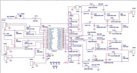
<LI class=navigation-list-item>TPA3116D2 in 2.1 master/slave mode I believe there is an error in the figure 27 schematic for a typical application of the TPA3116D" used in 2.1 master/slave mode.
U2 is in slave mode, the sync output from U1 fed via R73, 10k to the sync input with a 1nF capacitor C41 as a slew rate limiter. This reduces the swing on the sync input to around 1V peak/peak which in insufficient to sync U2.
In order to get U2 to sync I suggest C41 is reduced to 100pF to allow a full swing and the correct slaving of U2 to sync the two amplifiers.
John Hill
<LI class=navigation-list-item>TPA3116D2 in 2.1 master/slave mode I believe there is an error in the figure 27 schematic for a typical application of the TPA3116D" used in 2.1 master/slave mode.
U2 is in slave mode, the sync output from U1 fed via R73, 10k to the sync input with a 1nF capacitor C41 as a slew rate limiter. This reduces the swing on the sync input to around 1V peak/peak which in insufficient to sync U2.
In order to get U2 to sync I suggest C41 is reduced to 100pF to allow a full swing and the correct slaving of U2 to sync the two amplifiers.
An externally hosted image should be here but it was not working when we last tested it.
John Hill
- Reply Suggest as Answer Use rich formatting
- An externally hosted image should be here but it was not working when we last tested it.
Paul C. Chen
Hi John,
Yes the RC values need to be reduced. 4.7K Ohms and 47pF would work well. This is already noted for the next DS revision. Thanks.
reg,
Paul.
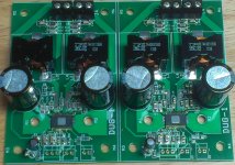
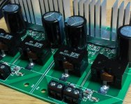
Decided to build a pair to use as "home theater" amp.
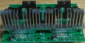
Nice heatsinks, you made them?
Nice heatsinks, you made them?
Sliced them on big band saw...cleaned up on stationary belt sander.
0.25" x 0.25" bar running across the bottom so board does not bend.
Had to notch a couple of places for C8 & R10 to clear by greater distance.
Tightened only just past point to compress split lock washers.
Last edited:
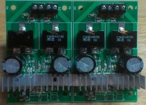
Hi, can you make another picture to see c8 and c11 from the side not from the front. ThanksDecided to build a pair to use as "home theater" amp.
Thanks a lot, now I have to fix both boards [emoji27] . Merry Christmas to all.
Thanks a lot, now I have to fix both boards [emoji27] . Merry Christmas to all.
Merry Christmas to you too! What do you feel you need to fix?
The positions of C8/C9 are not that critical.
The positions of C18/C20 are not that critical either.
If that is what you are concerned about.
The positions of C18/C20 are not that critical either.
If that is what you are concerned about.
Boards and IC's still available.
Did you want 2 pair or 4 separate boards?
IC's?
IC's installed/tested?
Did you want 2 pair or 4 separate boards?
IC's?
IC's installed/tested?
Hi DUG,
Do you have any stereo BTL boards left? I would be interested in one of these boards with IC soldered if you have any left.
Also could you post the schematic and BOM for the stereo BTL board? Perhaps I missed it, but could only see the PCB layout posted in #307.
Thanks
Do you have any stereo BTL boards left? I would be interested in one of these boards with IC soldered if you have any left.
Also could you post the schematic and BOM for the stereo BTL board? Perhaps I missed it, but could only see the PCB layout posted in #307.
Thanks
Hi DUG,
Do you have any stereo BTL boards left? I would be interested in one of these boards with IC soldered if you have any left.
Also could you post the schematic and BOM for the stereo BTL board? Perhaps I missed it, but could only see the PCB layout posted in #307.
Thanks
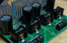
I have one that someone local changed their mind on.
Most of the parts are the same as for the PBTL board except for big caps and inductors.
Attachments
I have one that someone local changed their mind on.
.
Great! Put me down for one with the IC soldered.
Just wondering about the output inductors, what would you recommend that fits your board? Anything from this list?
Great! Put me down for one with the IC soldered.
Just wondering about the output inductors, what would you recommend that fits your board? Anything from this list?
The inductors for the DUG-2 are 0.55" in diameter. You could put a 0.64" square inductor on them if you put half of them on the bottom. (through holes available)
Did you want the kit or just the board with IC installed?
Send a PM to me with your e-mail for paypal invoicing. (and mailing address)
Boards and IC's still available.
Did you want 2 pair or 4 separate boards?
IC's?
IC's installed/tested?
Sorry for the delay. I'm just catching up after the holiday. I would take 2 boards if available. IC soldered and tested would be great but plain would be fine too. I'll PM you with my Paypal address. Shoot me an invoice and I'll pay ASAP.
Regards
- Status
- Not open for further replies.
- Home
- Group Buys
- GB for TPA3116/8 PBTL bare pcb