a couple of years ago I got a preassembled set from along1986090 on eBay and these days I thought I give it a try. As printed on the pcb, it is v9, the one with mosfet drivers
I am not sure why it behaves like that, is it a standard built? Initially I tried mine with a bench supply at +-50V and all looked ok. Then I connected to the ps I am going to use with, which gives +-72V dc and everything was fine. Even stressed it as much as I could and it didn't show any signs of instability.
I took some measurements at 8 Ohm load and max power is 198Wrms @8Ω just before clipping. Square wave looks fine, no sign of overshoot or ringing. DC offset was 11mV right, 9mV left and noise with input shorted on average 0.2mV in both channels.
Overall I was impressed as it performed great out of the box. Next, I will replace the input caps with a film type and connect to my system for evaluation 🙂
Guys,
Don't even try this. My L20s ran fine with +/-56V, and smoked when I put them on +/-68V. It also depends on the load, but stay away from high voltages.
I am not sure why it behaves like that, is it a standard built? Initially I tried mine with a bench supply at +-50V and all looked ok. Then I connected to the ps I am going to use with, which gives +-72V dc and everything was fine. Even stressed it as much as I could and it didn't show any signs of instability.
I took some measurements at 8 Ohm load and max power is 198Wrms @8Ω just before clipping. Square wave looks fine, no sign of overshoot or ringing. DC offset was 11mV right, 9mV left and noise with input shorted on average 0.2mV in both channels.
Overall I was impressed as it performed great out of the box. Next, I will replace the input caps with a film type and connect to my system for evaluation 🙂
Hi arg_. And what about the heatskin?? Was it hot?? How big is your heatskin? Can you post a picture???
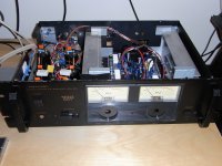
I used a piece of mdf to put the thing together plus two cheapish heatsinks I already had. When I was trying max power they got really hot and I had to make short bursts. If one is to use the best part of its power he will definately need either larger heatsinks or forced fan cooling.
However I have myself sensitive speakers and I am not gonna need more that 10-15 watts, at this level the heatsinks get only slightly warm

However I have myself sensitive speakers and I am not gonna need more that 10-15 watts, at this level the heatsinks get only slightly warm
Last edited:
Hello Everyone,
I've purchased 4 pieces of assembled L20V7 boards quite some time back and only recently decided to put them to use.
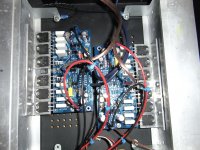
All boards were mounted directly on to heatsink without using any angle aluminum. This is done by curving the log transistor legs to position the transistor's back all flush against a single plane. Each was tested using a bench supply set at 30V (best it can do) and all were tested working.
Eventually I moved on to use the actual transformer I had which is a pair of 45-0-45 @ 400VA. Each transformer feeds into a 30A bridge and then into 18000uF caps. Each caps are also fitted with a 0.1u bypass cap and I also fitted a 150K load resistor across the + and - rails to discharge the caps when its off.
Problem starts when I feed this power supply to the boards. It will burn off the 0.1 resistor at the output stage and burns the output transistors together with 2 pcs of 100 ohm resistor. During the test stage with this bigger power suuply, no speakers was connected to the output. I replaced the damaged parts and tested again and this time another board burns.
I've tested for shorts between the transistors and the heat sink and again nothing connected to the output. I'm wondering if the rail voltage is too high. I would be feeding it with 63V+/-. Any ideas? I also realised that many people are talking about V9 but not so much on V7. Any kind advice?
I've purchased 4 pieces of assembled L20V7 boards quite some time back and only recently decided to put them to use.
All boards were mounted directly on to heatsink without using any angle aluminum. This is done by curving the log transistor legs to position the transistor's back all flush against a single plane. Each was tested using a bench supply set at 30V (best it can do) and all were tested working.
Eventually I moved on to use the actual transformer I had which is a pair of 45-0-45 @ 400VA. Each transformer feeds into a 30A bridge and then into 18000uF caps. Each caps are also fitted with a 0.1u bypass cap and I also fitted a 150K load resistor across the + and - rails to discharge the caps when its off.
Problem starts when I feed this power supply to the boards. It will burn off the 0.1 resistor at the output stage and burns the output transistors together with 2 pcs of 100 ohm resistor. During the test stage with this bigger power suuply, no speakers was connected to the output. I replaced the damaged parts and tested again and this time another board burns.
I've tested for shorts between the transistors and the heat sink and again nothing connected to the output. I'm wondering if the rail voltage is too high. I would be feeding it with 63V+/-. Any ideas? I also realised that many people are talking about V9 but not so much on V7. Any kind advice?
As lame as this can get, I found the problem to the burned board. I used a single transformer to supply the preamp and the speaker protection. Using a seperate transformer solved the problem.
LJM L25 (L20 variant)
Hi,
I have posted in another thread:
http://www.diyaudio.com/forums/solid-state/266498-ljm-l25-clone-modules.html
but received no responses then I found this thread and it seems to be more relevant to my LJM L25 clones. I have now tested the boards on the bench at +/- 30 VDC and they appear to work ok into an 8R test load. The L25 appears to be different from the L20 v9.2 in only 2 ways
a) It has a dual op-amp JRC4580 as an input pre-amplifier
b) It uses Sanken C2837/A1186 as drivers instead of MOSFET's
I will run at about +/- 55V in my amplifier chassis (a salvaged Realistic MPA-100). I hope it sounds as good as the L20 once all the errors (biasing, input capacitor) are corrected.
L25 input pre-amplifier
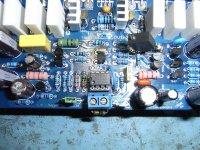
Starting to get a little bit concerned I have shelled out my hard-earned roubles on an LJM clone amplifier that no-one has heard of or used for that matter 🙁. Anyway, intrigued as to why designer had used a dual op-amp input pre-amplifier when the available seller documentation mentions a gain of only 4.7, I traced out the input pre-amplifier circuit. It appears to be a two-stage DC amplifier; first stage unity gain inverting with 10k resistors and second stage inverting with 2k2/10k resistors (gain = -4.5). Quite a strange configuration and not one I would have chosen. No need to use two inverting op-amps when a single non-inverting op-amp would be better (less noise contribution and very high input impedance). The first inverting stage defines the input resistance as 10k which might be a problem for higher resistance volume potentiometers. No DC blocking, pass-band filtering or RFI filtering - these are probably placed after the pre-amplifier stage but you want to avoid them from entering the amplifier in the first place. Looking at the overall amplifier design, it looks like an L20 with BJT drivers and a crude pre-amplifier bolted onto the front-end. In fact, the input sensitivity is quoted as "0.6V RMS 250W 8R power" so feeding from a DAC or CD player source, listening at normal levels, you would not need the pre-amplifier gain stage anyway! There must have been a glut of 4580 op-amps around at design time, might be time for a little re-work....hmmm, where did I put that Dremel?. Will keep you posted🙂
Starting to get a little bit concerned I have shelled out my hard-earned roubles on an LJM clone amplifier that no-one has heard of or used for that matter 🙁. Anyway, intrigued as to why designer had used a dual op-amp input pre-amplifier when the available seller documentation mentions a gain of only 4.7, I traced out the input pre-amplifier circuit. It appears to be a two-stage DC amplifier; first stage unity gain inverting with 10k resistors and second stage inverting with 2k2/10k resistors (gain = -4.5). Quite a strange configuration and not one I would have chosen. No need to use two inverting op-amps when a single non-inverting op-amp would be better (less noise contribution and very high input impedance). The first inverting stage defines the input resistance as 10k which might be a problem for higher resistance volume potentiometers. No DC blocking, pass-band filtering or RFI filtering - these are probably placed after the pre-amplifier stage but you want to avoid them from entering the amplifier in the first place. Looking at the overall amplifier design, it looks like an L20 with BJT drivers and a crude pre-amplifier bolted onto the front-end. In fact, the input sensitivity is quoted as "0.6V RMS 250W 8R power" so feeding from a DAC or CD player source, listening at normal levels, you would not need the pre-amplifier gain stage anyway! There must have been a glut of 4580 op-amps around at design time, might be time for a little re-work....hmmm, where did I put that Dremel?. Will keep you posted🙂
I have used the L-25's and had no problem with them till I ran a 3Ohm load through them @+/- 60Vdc and they blew up...totally my fault they are not rated for that voltage @4ohms let alone 3.
Took it for 20 minutes before they blew though 🙂
Took it for 20 minutes before they blew though 🙂
Cheers Paladinxxx, nice to know someone has at least powered a pair up all be it for a brief 20 mins before smoke 😀. I would err on the side of caution regarding any performance specifications published with clone modules, usually for "attention-grabbing" purposes. I will use a 50 - 55V supply, not intending to run them up to their maximum output. How did they sound while they were working?
Xslavic, the problem with clone amp modules is that schematics are usually not available and when they are, they have been tampered with or are incorrect. I have collected a batch of likely schematics for the L20 version that are available on this forum but nothing specific to the L25. As I said, the L25 is a modified L20 with an op-amp preamplifier bolted on the front end. That part is easy to deduct, just by looking at the board layout. If the L25 sounds good "out-of-the-box", then I can only improve by removing unnecessary components or reconfiguring as I have done with other clone amplifier modules. I see it as beating the cloners at their own game i.e. cloning the clone 😀
Xslavic, the problem with clone amp modules is that schematics are usually not available and when they are, they have been tampered with or are incorrect. I have collected a batch of likely schematics for the L20 version that are available on this forum but nothing specific to the L25. As I said, the L25 is a modified L20 with an op-amp preamplifier bolted on the front end. That part is easy to deduct, just by looking at the board layout. If the L25 sounds good "out-of-the-box", then I can only improve by removing unnecessary components or reconfiguring as I have done with other clone amplifier modules. I see it as beating the cloners at their own game i.e. cloning the clone 😀
Cheers Paladinxxx, nice to know someone has at least powered a pair up all be it for a brief 20 mins before smoke 😀. I would err on the side of caution regarding any performance specifications published with clone modules, usually for "attention-grabbing" purposes. I will use a 50 - 55V supply, not intending to run them up to their maximum output. How did they sound while they were working?
Xslavic, the problem with clone amp modules is that schematics are usually not available and when they are, they have been tampered with or are incorrect. I have collected a batch of likely schematics for the L20 version that are available on this forum but nothing specific to the L25. As I said, the L25 is a modified L20 with an op-amp preamplifier bolted on the front end. That part is easy to deduct, just by looking at the board layout. If the L25 sounds good "out-of-the-box", then I can only improve by removing unnecessary components or reconfiguring as I have done with other clone amplifier modules. I see it as beating the cloners at their own game i.e. cloning the clone 😀
The circuit structure is similar to that of the.L20,L25。 L25 increased the pre amplifier, in addition to the driving transistor.
They are free to design circuit I, not cloning. At least I have not found any manufacturers to adopt the circuit structure similar to.
They for higher power occasions. So the first stage amplifier is very convenient, but also to the higher voltage output.
If you don't need big power, then as MX50SE, small power amplifier or L6 is also very good more simple.🙂
Single stage audio amplifier
Hi LJM,
Thanks for taking the time to reply. I understand why you need the pre-amplifier circuit in the L25 to achieve the maximum output power, using an L20-like power amplifier stage. My query was why you needed a dual op-amp pre-amplifier to give an additional gain of only 4.7. This could easily have been incorporated into the power amplifier stage by adjusting a few resistor values. The op-amp configuration you have chosen to use is also quite unusual and does not fully utilise the best features of an operational amplifier. I have sketched your pre-amplifier in a configuration that I would choose. It uses all the same basic components as your design but just re-arranged them to make the best use of the op-amps characteristics, to deliver a circuit that will provide some amplification with minimal added noise or distortion. It is a classic text-book circuit with a few additional filtering components. It can be changed or modified in a number of ways to suit more specific requirements but bear in mind the impact on signal quality for significant changes. It is intended to be used with a typical volume control potentiometer in the range 10 - 50K.
I don't intend to discuss in detail the configuration of this text-book amplifier, it can be found in many electronics text. C1/R2 and C4/R5 set the audio band-width of the pre-amplifier (and following power amplifier). R4/R3 set the gain. C2a/C3a are ceramic surface mount capacitors mounted directly onto power supply pins of the op-amp. Surface mount components are very useful in audio amplifier design when used correctly can give significant sonic benefits. You can use any of your favourite op-amps, I use the Burr Brown OPA604 because I like its sound 🙂
I "listen" to this pre-amplifier every day in my usual amplifier system, a somewhat modified version used on your very own LJM Quad 405 clone modules with impressive results. Thank you for your continuing contribution to the DIY audio community.
Attachments

I used a piece of mdf to put the thing together plus two cheapish heatsinks I already had. When I was trying max power they got really hot and I had to make short bursts. If one is to use the best part of its power he will definately need either larger heatsinks or forced fan cooling.
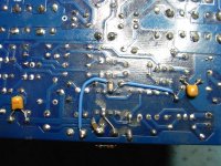
Poor pre-wired, wrong set of hetsinsks.
The circuit structure is similar to that of the.L20,L25。 L25 increased the pre amplifier, in addition to the driving transistor.
They are free to design circuit I, not cloning. At least I have not found any manufacturers to adopt the circuit structure similar to.
They for higher power occasions. So the first stage amplifier is very convenient, but also to the higher voltage output.
If you don't need big power, then as MX50SE, small power amplifier or L6 is also very good more simple.🙂
I found L 7 very good sounding but the L 20 I trew away.
LJM L25 amplifier power up test
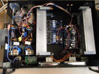
I have now assembled the LJM L25 amplifier modules and power supply in a salvaged Realistic MPA-100 case. I stripped out the original amplifier boards and transformer, retaining the 10,000uF filter capacitors, rectifier and heatsinks. I fitted an ILP torodial transformer and added another 23,300uF/rail capacitors with L and R filters to give a +/- 60 VDC supply. Out-of-the box, the L25 modules sound pretty good - lots of deep bass and plenty of authority, probably due to the 4 paralleled pairs of output transistors per channel 😀. Not quite so impressed with the top-end and mid-range detail, treble sounds a bit muted and dull though it is there. Also, at moderate listening levels, I can hear background noise from the mid-range speaker cone at my listening spot, which is volume-dependant.
With no specific L25 circuit diagram, I did a voltage check around the modules. Good news, the speaker output DC offset voltages were pretty low at -15.7mV (Left) and -4.7mV (Right). However, I could not measure any voltage across the 0.22R emitter output resistors so it would seem to be a pure class B output stage. This can be confirmed from the quoted quiescent current figure of 20mA per channel at +/-50V DC - not much, if any, of that current is likely passing through the output transistors. I located the Vbe multiplier 4K7/1K1 bias spreader resistors giving the required 6Vbe drops across the pre-driver, driver and output transistors. Just to check, I bridged the 1K1 with 2off series 8K2 resistors (16K4) and magically approx. 2mv appeared across each emitter resistor - ah well, approx. 10 mA bias current per transistor pair is (probably) better than nothing🙂. I listened to the amp but couldn't really hear any difference, vocals maybe a bit more forward in the soundstage. There might be room for further improvement here with an adjustable bias setting potentiometer but the trouble with a paralleled output stage is that to set an optimum output stage transistor bias of say 50 - 100mA (or even higher!), there are 4 transistor pairs so that means a large total quiescent current and very hot transistors/heatsinks 🙁. I would probably be more interested in trying to quieten down the mid-range noise. The quoted bandwidth of 5Hz - 300KHz seems unnecessarily wide to me, maybe a tweak around the input op-amp pre-amplifier and signal filtering components will help to reduce the background noise and enhance the mid-range/top-end detail. I will up-date on future progress but happy to hear from anyone who is using these modules and is enjoying the sound. Incidently, I have recently picked up a pair of LJM L25D (class D) modules for half the price of these modules so I could easily swap out the L25's and compare them, just for the hell of it 🙂
Attachments

Last edited:
L25 Modified
Ok, I just couldn't help myself and reached for the Dremel 😀. I re-configured the dual op-amp input pre-amplifier on the LJM L25 to now be a single non-inverting OPA604 unity gain stage. But, using a selectable jumper, I can increase gain by additional 5.5 times to be roughly consistent with the original design if required, to achieve maximum rated power into 8R. However, since I will most likely use amp with a DAC source at moderate listening levels, the unity gain configuration should be satisfactory and will reduce noise to a minimum.
Other significant changes:
a) Reduced the -3dB bandwidth from 300KHz quoted to approx. 85KHz (measured) by replacing 330p BW filter cap with 2n2.
b) Shunted the 1k1 Vbe multiplier resistor with an 8K2 + 10K multi-turn to set output stage transistor bias current between 5 - 85mA (set to 45mA).
c) Increased filtering on op-amp, 22uF + 1uF ceramic (original) + 10uF ceramic surface-mount directly on the op-amp PSU pins (33uF total)
d) Clamp the input ground resistor (10k) to the signal input terminal block, can easily be changed if required.
Tested module on bench into 8R load and no there were no problems. Will test in amplifier case and carry out listening tests. Will up-date on results shortly🙂.
Attachments
L25 Modification results
I have listened to the modified L25 and the noise issue has completely disappeared on the unity gain setting 😉 . Also, the mid-range and top-end detail has been restored and it sounds much more engaging and not fatiguing - a joy to listen to 🙂. There is only slight noise from the mid-range on the x4.7 gain setting at full volume, but its not really noticeable unless your ear in next to the speaker driver. Previously, you could hear the noise on moderate volume control level several feet away. I know the reconfiguration around the original dual op-amp pre-amplifier is responsible for the SQ improvement because I modified one channel first and compared directly with the unmodified channel. I have re-adjusted the output stage transistor idle to be 25mA/transistor pair i.e. 10 - 11mV across the 0.22R emitter resistors. This keeps the bias current more stable on my amplifier heatsinks, reduces heating and I could not hear any difference from the previous higher 45mA setting. The re-configuration changes are not difficult and well worthwhile IMO. I suppose now I had better find something else to "fix" 😀
I have listened to the modified L25 and the noise issue has completely disappeared on the unity gain setting 😉 . Also, the mid-range and top-end detail has been restored and it sounds much more engaging and not fatiguing - a joy to listen to 🙂. There is only slight noise from the mid-range on the x4.7 gain setting at full volume, but its not really noticeable unless your ear in next to the speaker driver. Previously, you could hear the noise on moderate volume control level several feet away. I know the reconfiguration around the original dual op-amp pre-amplifier is responsible for the SQ improvement because I modified one channel first and compared directly with the unmodified channel. I have re-adjusted the output stage transistor idle to be 25mA/transistor pair i.e. 10 - 11mV across the 0.22R emitter resistors. This keeps the bias current more stable on my amplifier heatsinks, reduces heating and I could not hear any difference from the previous higher 45mA setting. The re-configuration changes are not difficult and well worthwhile IMO. I suppose now I had better find something else to "fix" 😀
Hi
Some newbie questions:
For L20 V9.2 is there a "sweet spot" for a power supply voltage? I don't need more power but I need high fidelity.
May I use this Power supply:
Wholesale Product Snapshot Product name is 110V 220V 200W Digital Amplifier Power Supply board with Switching
until I will find a better one?
(Input voltage: 110-220V Output voltage: DC (+25 V) -0 - (-25V) 200W (+15 V) -0 - (-15V) (5W))
How many amps is needed here?
Thank you!
- Home
- Amplifiers
- Solid State
- L20 V8