Folks,
I am new to the forum, but have participated in a lot of chatter on Canuck Audio Mart over the years. I am often reluctant to sign up for new forums, because I like to keep it to the few, but after several nights of reading and sifting through some stuff on here, I have decided to become a member.
So, I was contemplating recapping my Toshiba SC335 power amp output stage. I downloaded the rough schematic that was available and it seems to be hand drawn and hard to read. I ordered a pair of Nichicon KG(M) Gold Tune caps to match the values in the amp. I took a little peek inside beforehand, but didn't inspect thoroughly.
When I received them, I figured it'd be a straight swap. But, then I realized the Marcon (Toshiba?) caps inside are 4 pole. I'm having a hard time determining whether they are 3 positive, 1 negative (in which case I could just use 4 caps?) or whether they are 2 input, 2 output poles? They seem to have a single shared negative terminal to the negative speaker terminal, but I am unfamiliar with this type of capacitor.
So, I am looking to the forum for some help or insight on this... Mostly looking to get the best out of the amp, as it is a great sounding one, I figure new caps would be a good place to start... If all goes well, I may consider replacing the ICs, but I am not getting any sizzling or anything, just decent sound. Eventually plan on recapping the pre amp as well.
Thanks guys in advance!
realco
"4 poles" did you mean 4 pins? I have seen big caps have 4 legs. 2 being connected to nothing, added for support of the big component on the pcb. you should look what those other pins are connected to on the pcb
Yes 2 of the pins are just to mechanically support the Marcon capacitors,. You might find a little bead of silicon around the new cap helps stabilize them. ( only around the outside of the cap - NOT underneath it)
By 4 pole I mean 4 lead. As far as I can tell they are not just to provide support. One cap has all four poles in use with wires connected. The other only has two in use.
Unless there's something I'm not seeing here? I read that some are 2 in 2 out. But, if they are purely for mounting purposes, can I just drop in two Nichicon gold tunes that I have? Same values....
Unless there's something I'm not seeing here? I read that some are 2 in 2 out. But, if they are purely for mounting purposes, can I just drop in two Nichicon gold tunes that I have? Same values....
Yes you can, but please please please make sure you connect them correctly. Getting it wrong or connecting to unused points on the PCB could spell disaster for the amp.
Refer to the circuit and the polarity markings on your caps and you'll be fine.
Refer to the circuit and the polarity markings on your caps and you'll be fine.
I was unable to do anything with the caps... I don't know exactly which wires should be going where...
Have you got any further details of the OEM part number of the original caps? Any identifying marks? Then you could identify them on a data sheet maybe? Maybe not, of course, but that's how I get the footprints and pinouts for the very large majority of components.

The board is to the back, with the wires coming out. You can see 4 pins on the right side of the board, and only 2 in use. But the other cap has 4 pins and all are in use? This is why I'm having trouble... But is this because of 4 speaker outputs??
An externally hosted image should be here but it was not working when we last tested it.
This picture is another one of the same amp, only branded as Aurex in Japan, not Toshiba. So, this one shows the PCB a little better... Looking at the PCB there are what looks to be only 3 how you say like signals? Only using 6 of the 8 potential leads. Is this to double up? Or?
The stock caps are Marcon 10000uf 50V... I don't know much about it thought?
Its nothing to do with the speaker outlets 🙂
You might find the original caps have continuity between each pair of pins (internally connected within the cap) and so that is used for convenience in the original design to simplify the layout and PCB layout. All that means is that you would have to link those pads on the PCB to replicate the internal connections in the cap... if that is how they are.
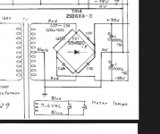
If you look at the circuit you can see that they are just two series connected caps. Same as any other symmetrical rail amp. The junction of the caps connects to the main amplifier ground. The "plus" terminal of the top connects to main +39 volt rail and the minus terminal from the bottom one connects to the main - 39 volt rail.
All you have to do is identify those points on those PCB's and wire accordingly.
You might find the original caps have continuity between each pair of pins (internally connected within the cap) and so that is used for convenience in the original design to simplify the layout and PCB layout. All that means is that you would have to link those pads on the PCB to replicate the internal connections in the cap... if that is how they are.
If you look at the circuit you can see that they are just two series connected caps. Same as any other symmetrical rail amp. The junction of the caps connects to the main amplifier ground. The "plus" terminal of the top connects to main +39 volt rail and the minus terminal from the bottom one connects to the main - 39 volt rail.
All you have to do is identify those points on those PCB's and wire accordingly.
Second picture...
Do those two sets of black wires read as being connected together. I can't see if the front pin with two black wires connects to the same bit of PCB that the pin with one black wire connects to. It looks like the pin is NOT connected to the PCB.
Can you confirm that ?
Do those two sets of black wires read as being connected together. I can't see if the front pin with two black wires connects to the same bit of PCB that the pin with one black wire connects to. It looks like the pin is NOT connected to the PCB.
Can you confirm that ?
More 🙂
If that front pin is not directly connected to the PCB then can you do this with the amplifier OFF...
Unsolder those two black wires that go to the front pin and then measure on low ohms range on your meter and confirm that those two cap pins are internally joined. This could be some attempt by Toshiba at creating a star ground.
Having done that, reconnect the wires back.
Now with the amp ON, measure the DC voltage on the other pins of both caps to determine which set of pins is PLUS 39 and which is MINUS 39 volts.
With that information it should be a simple case of fitting the new ones.
Removing the original caps should indicate which are pos and which are negative? There should be a line or indicator on the cap itself, no? I just wasn't sure why only one side was connected on the cap to the right?
Like, I would guess its from right to left (Not in use negative, positive, negative, positive)? As on the PCB the furhest right appears connected to the same as the negative on the other cap?
Like, I would guess its from right to left (Not in use negative, positive, negative, positive)? As on the PCB the furhest right appears connected to the same as the negative on the other cap?
Like, I can't figure why else it would have four leads? Doesn't make sense. The two ground (black) wires that come from the side are connected to the same lead and go to the negative speaker terminals, and are bridged across A+B negatives.
Like, when looking at the PCB, it looks like all the solder points are paired up. So, instead of using one simple lead as per my Nichicon caps, they have two. So, would I have continuity problems when using just the 1 lead and connecting multiple wires to it?
Removing the original caps should indicate which are pos and which are negative? There should be a line or indicator on the cap itself, no? I just wasn't sure why only one side was connected on the cap to the right?
Like, I would guess its from right to left (Not in use negative, positive, negative, positive)? As on the PCB the furhest right appears connected to the same as the negative on the other cap?
Yes, confirm visually which way round the caps go and write it down.
Like, I can't figure why else it would have four leads? Doesn't make sense. The two ground (black) wires that come from the side are connected to the same lead and go to the negative speaker terminals, and are bridged across A+B negatives.
The four pins on the cap are unusual but will just be internally linked in pairs. Don't worry over speaker connections, we are not altering anything there, just preserving the original scheme.
Like, when looking at the PCB, it looks like all the solder points are paired up. So, instead of using one simple lead as per my Nichicon caps, they have two. So, would I have continuity problems when using just the 1 lead and connecting multiple wires to it?
Lets try and make this easy. You connect each new cap to just the rear set of pads on the PCB. That leaves all the four front pads free.
Look at the picture.
Its up to you to determine the cap polarity... I can't tell from the picture.
Those two black wires essentially connect to the cap terminal above it but to preserve what could be an attempt at star grounding, keep the wires together and then connect them via a small spur of wire (any length, 2mm 22mm it doesn't matter). The words "cap connection" in the picture refer to the connection above that has the single black wire. It might seem illogical not just to join them all together at that point but its done this way for a reason to prevent ground interactions and problems.
Attachments

I truly appreciate your input. Specially Mooly for his diagram. I understand the circuit more now, but still have not done this. I know there are essentialy only three "pads" that connect these together. One communal negative it looks like, and two positives. So I would have to remove them to figure that out (there was no negative line to depict on the original caps).
I also just replaced a handful of key caps in my pre amp with Fine Gold Nichicons, in my phono path and two in my power supply path. I have ordered another slew to replace some more in my signal path, but I am damn near certain it sounds better already. I am honestly dying to replace these power amp caps, and I'm just trying to think how would I be able to do it... Hmm
I also just replaced a handful of key caps in my pre amp with Fine Gold Nichicons, in my phono path and two in my power supply path. I have ordered another slew to replace some more in my signal path, but I am damn near certain it sounds better already. I am honestly dying to replace these power amp caps, and I'm just trying to think how would I be able to do it... Hmm
- Status
- Not open for further replies.
- Home
- Amplifiers
- Solid State
- Recapping Vintage Toshiba Power Amp