Hi
just to commend.I skiped the smp for a trafo based PSU:2*18V/4,44A.driving both channels.retifiers and caps for each channel.
Not much difference in sound,exept the bass.
Firmer,more precise and more autority.
No noice.just a low thump when turning off.
BTW:The smp distubed my tv
Jan
just to commend.I skiped the smp for a trafo based PSU:2*18V/4,44A.driving both channels.retifiers and caps for each channel.
Not much difference in sound,exept the bass.
Firmer,more precise and more autority.
No noice.just a low thump when turning off.
BTW:The smp distubed my tv
Jan
Hi
just to commend.I skiped the smp for a trafo based PSU:2*18V/4,44A.driving both channels.retifiers and caps for each channel.
Not much difference in sound,exept the bass.
Firmer,more precise and more autority.
No noice.just a low thump when turning off.
BTW:The smp distubed my tv
Jan
Jan, can you please share what kind of psu or circuit are you using?
Could you please suggest a matching preamplifier (with volume control) for ACA amp, which can use same laptop brick (SMPS) power supply?
Looking at forums, many people are using B1 or DCB1 preamplifier.
B1 preamp requires only a single positive voltage from power supply where as DCB1 preamp requires both positive and negative voltages from the power supply.
Can we use the same laptop brick power supply which powers the ACA amp, or does these needs a separate linear power supply?
Also can we house both the pre amp and ACA amp in same cabinet?
thanks
S Sarath
Combining two laptop bricks with 2 x +/-? Maybe you should just build a separate power supply.
Combining two laptop bricks with 2 x +/-? Maybe you should just build a separate power supply.
means B1 preamp needs a single positive voltage. So can we put ACA amp and B1 preamp in same cabinet and both share the same laptop brick (single) of 90w power supply?
Hi
Jan
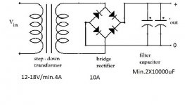
Very simple:see att.Jan, can you please share what kind of psu or circuit are you using?
Jan
Attachments
Hi Disorder. I recently built the B1 buffer preamp by Pass DIY here. Its a pretty simple circuit to build, uses the 2sk170's if you have any left over from the ACA, and can run from the same DC voltage supply of the ACA. It has volume control. The DIY store offers a more advanced printed circuit board.
I can't offer any advice on the best practice to implement a volume control though, sorry.
I can't offer any advice on the best practice to implement a volume control though, sorry.
Hi Disorder. I recently built the B1 buffer preamp by Pass DIY here. Its a pretty simple circuit to build, uses the 2sk170's if you have any left over from the ACA, and can run from the same DC voltage supply of the ACA. It has volume control. The DIY store offers a more advanced printed circuit board.
I can't offer any advice on the best practice to implement a volume control though, sorry.
how does it sounds with B1 peramp powered by same SMPS power supply of ACA amp?
Is it good or bad when compared with having a separate dedicated linear power supply for B1?
how does it sounds with B1 peramp powered by same SMPS power supply of ACA amp?
Is it good or bad when compared with having a separate dedicated linear power supply for B1?
I'll test tonight and let you know if I can hear any difference.
Hi
just to commend.I skiped the smp for a trafo based PSU:2*18V/4,44A.driving both channels.retifiers and caps for each channel.
Not much difference in sound,exept the bass.
Firmer,more precise and more autority.
No noice.just a low thump when turning off.
BTW:The smp distubed my tv
Jan
I don't doubt that you hear a difference, but do you have a thought as to why your psu setup would give better bass?
I struggled with the thought of the smps bricks from the beginning given Papa's choice to use them was for simplicity at the amp camp and not for sound quality. But as the article said I quickly "got over it." Mostly!
Could the slight difference in output (18v, 4.4a vs 19v 4a) or an even lower noise floor (Papa tested output noise at 100uV using the bricks) impact the sonics? Others here have spent hours and money upgrading the power supplies so it's not just Jan.
I am a newbie and I have internet not real electronic knowledge. Mine is a desktop system in a small spare bedroom that can get a slightly warm on a summer day. The Alpair speakers are not efficient but they are less than 3 feet and Pano’s voltage test tone says I am using 1/2 watt on average. I realize the ACA runs hotter at this low level. I have read the thread and I believe the ACA dissipates 28 watts with the resistor mod. Is this at idle? Google says that incandescent light bulbs are 10 % efficient. Am I mistaken in thinking this is about the same heat as a 30watt light bulb? I think I can make some changes in the room to offset the additional heat but let’s suppose I am wrong. Since I do not need the power is it significantly bad sonically to dial the voltage to 14-16 v?
One of the reasons I want to replace my AB amp is that it has developed a bad turn on thump. If a put a say 10mH choke between the ACA smps and a 10K cap, to reduce the turn off thump, would the smps “see” the capacitance (of the cap) as a potential problem?
Finally I am using autoformer volume controls so no DC. Can I remove the input 10uf cap and maybe a resistor? Thanks to Papa and those who help him.
I would put the devices near 4.5 A/B and 4.5 C/D. That is near bottom of sink and spaced apart. No expert, Just my two cents...I'm in the design/gathering materials stage of an ACA build (mono blocks). The heat sink for each block will be approx. 4" x 7", vertically oriented (fins vertical also), but tilted back 45 deg. Using the attached layout grid, what do you think would be the best placement on the heat sink for the two output devices?
Thanks...
Last edited:
How was the testing ... What were your impression with different power supplies ?I'll test tonight and let you know if I can hear any difference.
One of the reasons I want to replace my AB amp is that it has developed a bad turn on thump. If a put a say 10mH choke between the ACA smps and a 10K cap, to reduce the turn off thump, would the smps “see” the capacitance (of the cap) as a potential problem?
Finally I am using autoformer volume controls so no DC. Can I remove the input 10uf cap and maybe a resistor? Thanks to Papa and those who help him.
I am not due a response but perhaps in this season someone might feel the urge to opine even if certainty is not possible.
Last edited:
I am not due a response but perhaps in this season someone might feel the urge to opine even if certainty is not possible.
You need the input coupling cap to allow the bias voltage to develop on the SK170 gate. If. You use an autoformer that provides a DC path to ground, that would prevent the proper bias voltage from being there. So the cap does two things: it prevents any DC present in the input signal from interfering with the Jfet Gate, and it prevents the bias voltage from draining away through the input source. The resistor there is so the bias voltage from the bias pot can get to the Gate of the Jfet.
It needs to be there.
I don't understand the rest of your question so I hesitate to try to answer about that.
I can tell you that the amplifier is Amazingly good the way it is originally designed. I recommend building it exactly like it was intended.
Last edited:
The ACA switching supplies I have seen will charge a 10,000 uF cap. If they
don't there is a simple addition using a resistor and a diode to provide slow
charge for the cap.
An LC filter with lesser values of capacitance will still help with the noise figure,
so feel free to try it.
😎
don't there is a simple addition using a resistor and a diode to provide slow
charge for the cap.
An LC filter with lesser values of capacitance will still help with the noise figure,
so feel free to try it.
😎
I would put the devices near 4.5 A/B and 4.5 C/D. That is near bottom of sink and spaced apart. No expert, Just my two cents...
Thanks Mike, that's what I was thinking also, although I thought there might be another scheme given the vertical orientation of the sink.
Hi Chuck...Thanks Mike, that's what I was thinking also, although I thought there might be another scheme given the vertical orientation of the sink.
I was thinking about you mentioning that the sinks will not be exactly vertical. If you were putting the sinks horizontal (with fins straight up) I would think devices centered in the sink would make sense. Since you are in between , maybe up a little higher would make sense. I think the original kit had them mounted lower since that would be the place where cooling air would be entering.
- Home
- Amplifiers
- Pass Labs
- Amp Camp Amp - ACA