I think it's the final revision of layout , I done everything was necessary /suggested ,even more with personal contribution
Regards,Alex
Yes Alex you've done all, and it is excellent job. Just one thing you don't want to change, capacitors for DC servo, C18 and C19, and I don't understand why.
Cheers, Damir
Just one thing you don't want to change, capacitors for DC servo, C18 and C19, and I don't understand why.
Cheers, Damir
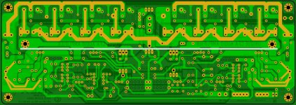
Sorry to tell you but those caps are in place , just look closer in yellow first pic, and red circle in the second pic ....🙄
Alex
Attachments
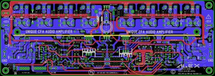
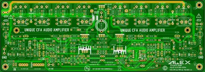
Sorry to tell you but those caps are in place , just look closer in yellow first pic, and red circle in the second pic ....🙄
Alex
Oh yes, I was looking the same position where you still have 5mm spacing and did not notice added caps. My apologies for that.
Now we have the PCB with all output transistors on one side and two possibility to fix it to the heat sink, perpendicular and parallel. I prefer perpendicular as in that way the PCB and electronic components are less heated from the hot heat sink, but if someone like to put it parallel it is possible now.
Thank you Alex, I still did not finish connection check, how sure you are that all is correctly connected?
regards, Damir
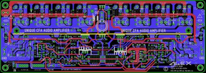
PCB rev 2.5
I have check again ,found only one bad connection ,corrected now ,and I think are no more errors IMHO 🙂 so we can move ahead.....
Alex
I have check again ,found only one bad connection ,corrected now ,and I think are no more errors IMHO 🙂 so we can move ahead.....
Alex
Attachments
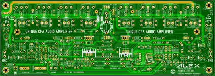
PCB files for toner transfer
PCB toner transfer files are attached 🙂 may be someone will make to sing ....
Regards ,Alex
PCB toner transfer files are attached 🙂 may be someone will make to sing ....
Regards ,Alex
Attachments
Hello.
Has anybody built a prototype yet?
I think here is the schematic: http://www.diyaudio.com/forums/solid-state/253039-unique-cfa-120-230w-amp-2.html#post4113328
Has anybody built a prototype yet?
I think here is the schematic: http://www.diyaudio.com/forums/solid-state/253039-unique-cfa-120-230w-amp-2.html#post4113328
Hello.
Has anybody built a prototype yet?
I think here is the schematic: http://www.diyaudio.com/forums/solid-state/253039-unique-cfa-120-230w-amp-2.html#post4113328
No, not yet.
Damir
It looks great🙂 what about the 120W version, do you have PCB for that or Sell PCB's, maybe as group buy?
It looks great🙂 what about the 120W version, do you have PCB for that or Sell PCB's, maybe as group buy?
Alex made the layout for 200W version, 120W version does not have a layout yet.
I am planning to make the layout for 120W and 200W versions with ThermalTrak OPS.
Before group bay I have to make a prototype, and I am quite slow.
I look forward to buy 120w PCB🙂 as i have everthing else to build a complete amplifier🙂
Thanks again for great project.
Thanks again for great project.
I'm ready to buy 200W pcb version when ready... let me know order details, pls.
THx-RNMarsh
Hi Richard, I don't want to sell any board before I build a prototype. Problem is that I can't buy all needed part in short time, some are quite expensive, so it will take some time to do that, be patient with me.
BR Damir
In post #105, Alex has posted a double sided PCB layout, but no Gerber files. I am not sure if this was intended for iron-transfer method, but connecting every 'via' is challenging as much as aligning the top and bottom layers.
However, with some suggestions from anyone here, I offer to assemble and test the prototype, so that the Group Buy can be arranged.
If Alex can share the Gerber files, I could get a local manufacturer to produce sample boards and after testing the actual production boards. I believe the cost and quality should be comparable to the best boards from China.
Dadod do you have news?
🙂
Today I received my boards for LMOSFET in TO3 cases, so now I have to check what components I am missing.
Here are the Loop Gain(LG) and 1 kHz FFT at 1 W/8 ohm.
BR Damir
Hello dadod,
I would like to know the meaning for the loop gain plot phase starting at +90 degrees.
It seems that your circuit could use 270 degrees before reaching the gain margin point.
Hello dadod,
I would like to know the meaning for the loop gain plot phase starting at +90 degrees.
It seems that your circuit could use 270 degrees before reaching the gain margin point.
Sorry, could you be more specific, I don't understand what you ask?
Sorry, could you be more specific, I don't understand what you ask?
In #16, you posted the loop gain plot.
The plot shows that the phase starts around +40 degrees from the left, but I think it should go from +90(or -270?) degrees from the left and decrease towards the right.
I believe normal loop gain plot phase should start from 0 degree and decrease.
Is it ok?
What trick is used to do so?
And, why does normal loop gain plot phase start from 0 degree?
This depends how DC servo was connected for the LG simulation, before or after Tian probe. In this case it's connected to the amp output, if connected after Tian probe phase start from 0 degree.
When I simulated this LG I wanted to see DC servo influence on the Loop Gain.
- Home
- Amplifiers
- Solid State
- Unique CFA 120/230W amp