When you say, it's going to fail again, do you mean it had failed outright before, or you just mean, it will get hot/burn again? was it at any point not working before you decided to replace the resistors?
You said you put much larger ones in - larger ones of the same value, or ones with a higher resistance?
thx.
It hasn't failed before. It was working perfectly, but if I left it that way, it was a matter of months before it was going to fail, traces were already coming loose. So, a preventive action.
Now it's a matter of years, I think. I don't think it's going to burn again (the resistors are far enough from the board), but it is just not mended 'properly', as a good technician would say. The burned area is still there, and traces will get loose after some time, even cracks might occur (even if the source of the heat is taken away). The black coloured area (=carbon) is also (slightly) conductive and of course that's not good.
I put higher power resistors (physically larger) in, but of course of the same resistance.
But if your amp does not have that problem, you don't have to do all this. If the resistors aren't getting hot, there's no problem.
Gotcha, thanks for the additional clarity. I'm going to pull mine apart this evening and check for signs of burning/damage. It had been working fine for a week after I bought it, and I suspect the previous owners baby'd it. Naturally, my first action was to load up some bass heavy tracks and test the snot out of it (wish i'd read this thread first). My initial thinking is some problem with the muting circuit... Or the caps not charging in time before the sub goes to full power after initial activating, causing the strained squawk/groan... But I don't know what I'm talking about for the most part 🙂
Last edited:
Gotcha, thanks for the additional clarity. I'm going to pull mine apart this evening and check for signs of burning/damage. It had been working fine for a week after I bought it, and I suspect the previous owners baby'd it. Naturally, my first action was to load up some bass heavy tracks and test the snot out of it (wish i'd read this thread first). My initial thinking is some problem with the muting circuit... Or the caps not charging in time before the sub goes to full power after initial activating, causing the strained squawk/groan... But I don't know what I'm talking about for the most part 🙂
Ah, something else, does your 'squawk' sound like this?
JBL sub 'squeaking' - YouTube
Ah, something else, does your 'squawk' sound like this?
JBL sub 'squeaking' - YouTube
Nope... The driver isn't bound in anyway or making any mechanical sounds... Its an actual audio signal of some sort, and only at initial start (coming out of standby).
I have a dead PB12 that I started to tear apart for giggles. Pretty quickly I could see that C11 on the PWRAMP board was, well, non-existent. I also found a few dead resistors. C10 is also domed, so I'm replacing it while I'm there...
I was able to order the resistors, but I'm having trouble finding the proper cap to replace C11. C11 is a 330nF 100v 20% mono ceramic cap according to the service manuals. It is rectangular, and I'm having no luck on digikey or mouser finding one that appears to be the right fit.
Any suggestions? Since it's fried, I'm taking shots in the dark here.
and yes, I realize this probably isn't worth my time given the problems witht he board, but hey, what else am I gonna be doing? 🙂
This might be a very old, very dead thread...
But I finally designed a solution for the S64AMI S53AMI and it works well.
So well in fact, I may be putting out too much power because it bottoms out the subwoofer.
Very stable, and works awesome! I am in the state of refinement though. Got some bugs to work out, and tweaks to make to roll on a new PCB, you may see those little tweaks in the pictures i posted.
Have a look.
The only thing left to work out is heatsinking. I dont feel like routing out the original epoxy potted junk. I decided to mount the output transistors on the opposite side of the board, and use VIA stitching to transfer heat through.
My thought was a sil-pad and a small heatsink.
This thing does not get very hot even at full continuous power. maybe 110F. The thing to watch out for, is the carrier wave falls drastically in frequency as the modulation goes up, I guess a byproduct of SOD. This will overheat the filter components if not careful. I may go with fixed freq in the next design. But this current design runs around 250Khz or so. Sounds pretty good at full range.
Attachments
Last edited:
I didnt have a choice. I have 4, maybe 5 of these things sitting in the shop, I had to come up with something. Couple 10s, couple 12s, even a 15, got another 12 but its a V2 amp so no issue.
Once I get the design finalized, I think i will offer the modules for sale on eBay, and maybe even offer the swap and modification service.
Once I get the design finalized, I think i will offer the modules for sale on eBay, and maybe even offer the swap and modification service.
I didnt have a choice. I have 4, maybe 5 of these things sitting in the shop, I had to come up with something. Couple 10s, couple 12s, even a 15, got another 12 but its a V2 amp so no issue.
Once I get the design finalized, I think i will offer the modules for sale on eBay, and maybe even offer the swap and modification service.
Great effort and great idea - for sure lots of (DIY) people will benefit from it.
Time to grab some busted units on eBay for almost nothing... 🙄
Cheers!
D
Just an update: My version 1 board is still running flawlessly, but due to the choice of outputs I used, and heat issues, I had to increase the dead-time thus losing a bit of fidelity.
But hopefully my version 2 fixes these little issues.
But hopefully my version 2 fixes these little issues.
Sorry for the long pause in updates, But...
I ended up running out of R&D funding for the project, so it was never 100% completed. I did manage to get a subwoofer working, but it didnt quite sound right as I needed to change a few aspects of the design. Plus the main board needed some slight modifications, the 6V circuit needed to have some components changed to support 15V gate drive voltage. Then the 10uF cap needed changed in the output to a film cap. Also there was an op-amp stage that needed jumpered around, bypass, plus a feedback resistor change. So it was never intended to be a "drop in" replacement. I was going to offer a repair service though if it were to succeed.
Funds were eventually cut, and then I no longer work for that company. I moved onto bigger and better things.
Sorry, I may release my latest design files though.
My solution DOES in fact work! Just have to perform the modifications I had scribbled in the previous picture, and do some tweaking.
Last edited:
Attached were the last design files I had created before the project was toasted.
The component values are good enough to get it working.
But the front-end needed some component value tweaking to get the frequency to match better with the JBL output filter stage configuration, as since this is self-oscillating the frequency has a tendency to dip too low on high modulations causing overheating in the output filter stage. Lower volumes were perfectly fine though.
the 2nd thing I needed to do was change the output transistors to TO-220 for better custom heatsinking. I chose the surface-mount versions so I could slide the board and sink it inside the original S64AMI heatsink shroud, but that never happened because potting...
So I increased the width of the board, and never got around to changing the output configuration, Also the board needed to be converted to fully surface mount which didnt happen yet.
Also, the IRFB4229s I chose were a little too much for this design as well, because R3 has to be tweaked for minimum heating, but it affected the fidelity of the amplifier.
You will have to play around. it does work though! This Design was tested with the amp shown in my previous photos, and I believe it was a +/-90V Rail system.
Here is the DropBox link:
https://www.dropbox.com/s/hqy0lgnqd04npnn/S64AMI.rar?dl=0
I had to use dropbox, because DIYAudio's file extension and attachment system is still stuck in the 1980s.
Last edited:
File no good
The file in dropbox will not open. Where are you located? I like to tinker but unfortunately I'm not literate in electrical techno babble. I'd have to watch a video showing me step by step what needs to be done in order for me to do this myself. Would you be interested in doing the mod if the amp were shipped to you? I upgraded the sub to an Infinity 120.9 and it sounds like there are about 5 PB12's in the room when it works. My 2nd amp finally died.
The file in dropbox will not open. Where are you located? I like to tinker but unfortunately I'm not literate in electrical techno babble. I'd have to watch a video showing me step by step what needs to be done in order for me to do this myself. Would you be interested in doing the mod if the amp were shipped to you? I upgraded the sub to an Infinity 120.9 and it sounds like there are about 5 PB12's in the room when it works. My 2nd amp finally died.
Are there still people out there with blown amps that have the S64AMI module?
I have been working on a drop in replacement for the module and I think I will have a nice solution. I have a schematic and PCB designed, I just need to have the PCB fabricated, order the parts, assemble and test. This is still pretty far from being done but I'm hoping to keep interest going until I can get it done.
I have been working on a drop in replacement for the module and I think I will have a nice solution. I have a schematic and PCB designed, I just need to have the PCB fabricated, order the parts, assemble and test. This is still pretty far from being done but I'm hoping to keep interest going until I can get it done.
S53AMI module reinstallation
Hi all
I was attempting to fix my GF's JVC SXPW650 subwoofer that has a S53AMI module and I have found that the mossfets were shot so ordered a set at Digi with a fuse BUT now that the module is out of the AMI case I have just seen on the board that the screws that held the module in place seems to have a circuit each. So now I'm wondering what must I do now that the module is out of the case (and don't have it no more). I have provided 2 pics to show what I mean. Now what is this circuit??? DO I just make a simple jumper wire to each other OR….. So for now my fix is on hold because I have no idea what to do about this. Any help would be much appreciated!!!
Serge
Attachments
Wow, I didn't notice this post so this is pretty delayed.
However, I'm pretty certain that you don't need to jumper those connections. Those pads for the mounting screws should just be connected to ground and I'm assuming if you looked on the other side of the board, you would see ground connection to those holes. I'm not sure on your unit because I don't have the same one as you.
The thing you have to worry most about is proper heat sinking. I had problems with making a decent heat sink to my FETs.
I decided to make my own version of the board. (See following post)
I have finally had my design fabricated.
It is a very simple design that uses an opamp to make the ramp and integrator, then a FET driver IC with 2 pretty nice FETS.
It also uses the incoming rail voltages to create a +15V supply referenced to the bottom rail so the FETs can be properly driven.
As long as I did it right, this should be a drop in replacement for the S64AMI module.
I will post a schematic soon.

My PB12 died years ago. I just disconnected the wires to the speaker (to bypass the amp plate), dropped an Adcom GFA-545 power amp on the top of the PB12 and ran the speaker wires through the port then to one side of the Adcom. Been running it that way for years. The only downside is that I have to manually turn on/off the Adcom.
Better late, than never...
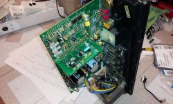
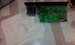
I enjoyed reading the 36 pages of history regarding the S53AMI and the work Pat and the rest of the passionate ones attempt to gain the trophy of fixing this consumer's nightmare.
My first run down the rabbit hole was just as frustrating as the next man's headache dealing with poor quality production hiding behind a GRADE A badge. The first quick jabs I was hit with:
Item 3 reminded me of a period where Alpine's car amplifiers were having similar conditions, which required a 12-pack and a couple hours checking and reworking the circuit boards to get them operational again... No component failures, just could not handle the heat and would just go into protection mode and shut down. Power-cycle the amp, lower the drive capacity and increase cooling operations might get you to post up at the club with the right bass-line.
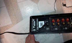
I diagnosed the patient and called the cause before I even disconnected the system and opened it up. I had verified basic properties with a DMM to quantify my intuitions. Sure, these powered sub-woofers will run fine, for years, if your drive them like a grandmother going to bingo night and the VFW. Open her up, kick out the cobwebs and let the rhythm move the neighbors and Pandora's Box is open for suggestive troubleshooting / operations.
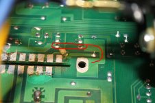
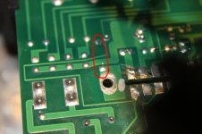
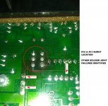
You can see what I mean in the image, as the rings in the joints identify the conditions I speak of. Yes, the sub could work well for a week or two, hiccup for the same period or just have a meltdown in the middle of the freeway. Your flip for the ball...
I am not sure how much I will spend trying to eradicate the demons from the design, but I am already thinking of dropping in a design change relatively quickly and as painless as possible (I HOPE).
SO, I AM TEEING OFF FOR THE 1ST HOLE. MAY MY ROUND BE SUB-PAR (HAAAHAHAHA).
I enjoyed reading the 36 pages of history regarding the S53AMI and the work Pat and the rest of the passionate ones attempt to gain the trophy of fixing this consumer's nightmare.
My first run down the rabbit hole was just as frustrating as the next man's headache dealing with poor quality production hiding behind a GRADE A badge. The first quick jabs I was hit with:
- Woofer wired 180 degrees out of phase, previous owner mentioned lack of drive.
- R10 & R13 campfire evidence.
- Multiple weak soldier joints, typically caused by high heat & poor cooling.
Item 3 reminded me of a period where Alpine's car amplifiers were having similar conditions, which required a 12-pack and a couple hours checking and reworking the circuit boards to get them operational again... No component failures, just could not handle the heat and would just go into protection mode and shut down. Power-cycle the amp, lower the drive capacity and increase cooling operations might get you to post up at the club with the right bass-line.
I diagnosed the patient and called the cause before I even disconnected the system and opened it up. I had verified basic properties with a DMM to quantify my intuitions. Sure, these powered sub-woofers will run fine, for years, if your drive them like a grandmother going to bingo night and the VFW. Open her up, kick out the cobwebs and let the rhythm move the neighbors and Pandora's Box is open for suggestive troubleshooting / operations.
You can see what I mean in the image, as the rings in the joints identify the conditions I speak of. Yes, the sub could work well for a week or two, hiccup for the same period or just have a meltdown in the middle of the freeway. Your flip for the ball...
I am not sure how much I will spend trying to eradicate the demons from the design, but I am already thinking of dropping in a design change relatively quickly and as painless as possible (I HOPE).
SO, I AM TEEING OFF FOR THE 1ST HOLE. MAY MY ROUND BE SUB-PAR (HAAAHAHAHA).
Attachments
- Home
- Amplifiers
- Class D
- JBL PB12 subwoofer, Class D amp, dead.