That's interesting. To be quite honest I've not done any more than glanced at the TPA3116 datasheet so I wasn't aware of the 1SPW option.
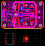
I did take a quick look (see attached) and I could probably make a TPA3116 fit on the board. I considered doing this but looking at my usual suppliers (Farnell, Digikey & Mouser) the TPA3116 is around double the price of the 3132 for small quantities, which is a surprise. I wonder why?
I've had a look around for 41Hz audio gear and there's an awful lot about it but it seems they have now disappeared? I might add that it seems odd to supply small size SMD designs as kits, but regardless they are clearly popular. Also saves on assembly overheads I suppose.
This is my first post here other than the introduction, so hi )
So earlier this year, a friend of mine had a cheap class D amp from ebay and it broke (turns out the battery wasn't charged...). He was pretty fed up with cheap ebay stuff so he asked me if I could build a better one.
A browse through TI and I settled on the TPA3132. This is basically the same as the TPA3116 (I think) but in a QFN package. The first set of boards were 1.5x2.5" in size and were just the datasheet schematic. I was completely lazy and just stuck everything in one ground plane and didn't pay much attention to the layout.
So we built a few of the boards and even with the sloppy layout they sounded MUCH better than the ebay ones, and were already much smaller. He had paid for all the parts so he took the boards and left me one to play with. I gradually cut the thing up and tried different components to improve it as one of my projects on the side.
Fast forwarding to now, I've completed the assembly of a new amp, which measures 1.5x1", by about 3/4" high when populated, uses the TPA3132 with ferrite bead output filters, has far more responsible use of ground planes among other improvements. I also shoehorned screw terminals and connectors onto it, so it can be used with no soldering. BTW the input is single ended, as the idea of this thing is just to be plugged into a phone or something.
By comparison to my composite LM3886 amp, the difference in sound quality is only just noticeable (to my ears). It doesn't affect any of my FM radios that are at least a meter away or so, but obviously still radiates (depends mostly on speaker wire length). It also barely gets warm when running on max volume. Works great off a laptop power brick, or a battery if you want a portable set of speakers.
As for the specs, the gain is 32dB with an input impedance of 15K. The output power is 2x25W(8Ω) 2x50W(4Ω), and it runs on anything between 4.5V-22V.
I realise not everyone needs such a small amp, but I've built 10 so I'll keep one for me and sell 9, if anyone is interested. Would be perfect for a set of portable speakers. Note that they are hand assembled, so some of the boards have a bit of excess flux etc... on the non-reflowed components, but all work well. I've made up 500mm long 3.5mm jack to the 3-way female header sockets to mate with the amp. I couldn't fit a normal jack socket on the board as I ran out of room.
I was thinking maybe £17 each plus postage or something (hopefully not asking too much). That would allow me to cover the costs of the boards, which is fairly important as I'm a student 😛 . I'm in the UK so 93p postage to the UK, for other places I'll have to look it up. I've written a little manual with mounting hole dimensions and some other stuff in, that will be included with each board.
Anyway this thread isn't just trying to sell these things, any and all questions/criticisms are welcomed. But if you are interested in one, let me know.
(Reading it back it looks like I have something against items from ebay, what I mean is cheap crap from ebay 🙂 )
Very nice job! I love how small they are.
Now sit back and see how long it takes YJ or one of the other Chinese manufacturers to take your design and sell it in mass. That is how we ended up with the famous YJ blue/black TPA3116D2 amp designed by member Danzz.
Very nice job! I love how small they are.
Now sit back and see how long it takes YJ or one of the other Chinese manufacturers to take your design and sell it in mass. That is how we ended up with the famous YJ blue/black TPA3116D2 amp designed by member Danzz.
Thanks! Although I suppose it's a sign that you have got somewhere in life when China copies your products 😀
That's interesting. To be quite honest I've not done any more than glanced at the TPA3116 datasheet so I wasn't aware of the 1SPW option.
I did take a quick look (see attached) and I could probably make a TPA3116 fit on the board. I considered doing this but looking at my usual suppliers (Farnell, Digikey & Mouser) the TPA3116 is around double the price of the 3132 for small quantities, which is a surprise. I wonder why?
I've had a look around for 41Hz audio gear and there's an awful lot about it but it seems they have now disappeared? I might add that it seems odd to supply small size SMD designs as kits, but regardless they are clearly popular. Also saves on assembly overheads I suppose.
To take the last bit first. Yes, they were supplied as kits but the SMD parts were of physically largest kind that could fit in order to make it possible for even reasonably novice builders to DIY.
As you can see from this picture below the TA2021 is much larger than the TPA3116 (similar size to STmicro HSSOP36 size) so it is certainly possible. And it had full LC output filter as was required for that chip as it did not feature a filterfree operation mode like is standard on the TPA3116 (and the only option on TPA3132).

The size of the chip especially it's thickness allowed other components to mounted on the same side without interfering with the direct heat slug to cabinet bolting. Just like a TPA3116 a regular heat sink isn't really needed. To do the same with the TPA3116 you'd probably need some heat transfer material in order to fit components on the same side as the chip as the TPA3116 is too thin to allow this otherwise.
It's important to note that if you want to experiment with the 1SWP modulation mode on the TPA3116 that is it not a filterfree modulation mode. You must use full LC output filtering which leads me back to one of the most interesting parts on the amp32, the custom made dual output inductors. The only writing on them is "100 QY-" and I have no idea who made/makes them but they are very similar to the ones referred to below. It's the same incredibly compact physical package and most of the characteristics are the same as well.
http://www.xfmrs.com/pdf/XF100910DL-xxxx.pdf
Last edited:
Those inductors are rather interesting. A look on the XFMRS website showed no results, so I can only assume that the particular series in question is out of production. I'll drop them an email and see what they say.
As for heatsinking, the TPA3132 has the pad down of course, and with a fair bit of via stitching to the other side of the board I've had no issues with heat. Into a 4 ohm load at max input voltage it gets hot, probably about 60-70C. But at that power it distorts like hell anyway, and during all normal use it just rises in temperature, but doesn't get warm.
Out of interest how much did the amp32 kit cost? It looks like they used a thick board and decent components, a guess from here would be about $10 BOM for small batches.
Also, I went to a bit of effort to source nice Camdenboss screw terminals and fit them on the board. Without the terminals I could decrease the size, although this would remove the plug and play capability. What are your thoughts on this?
Last edited:
If you're using the TPA3116 it's probably advisable to use an inductor capable of the full current even though it would hardly ever be used but it ensures you're reasonably safe even with low impedance loads. Coilcraft HA4158-EL (and similar) are still compact enough to fit but has even better data.
The idea behind using the TA2021 which is slug up (similar to TPA3116) instead of the TA2024 which is slug down (similar to TPA3118) is that you can route power plane directly under the chip and have ground plane exclusively on the reverse side. This makes routing far more optimal at the expense of requiring some kind of heat spreader, usually the casing itself.
I prefer (vertical) pin terminals for such compact boards. Screw terminals really takes up a lot of room, and anyone using such compact boards probably don't mind the small extra hassle. There's a lot of options of larger boards with screw terminals around for the multi-thumbed people.
I think the kit was €25 shipped. Board was quadruple thickness copper. All components were hand picked from an engineering point of view rather than "audiophile" preferences which usually gives the best end result.
IO390, can you find out how much shipping would cost to Mumbai, India? Slipped into just a padded envelope.
If you're using the TPA3116 it's probably advisable to use an inductor capable of the full current even though it would hardly ever be used but it ensures you're reasonably safe even with low impedance loads. Coilcraft HA4158-EL (and similar) are still compact enough to fit but has even better data.
They look like nice inductors. Not cheap though, to use such parts would increase the cost of the board by about £4-5, so if I was going to invest in a batch I'd have to be sure I'd have interest. Still, £22 or so isn't too bad... Or is it?
I prefer (vertical) pin terminals for such compact boards. Screw terminals really takes up a lot of room, and anyone using such compact boards probably don't mind the small extra hassle. There's a lot of options of larger boards with screw terminals around for the multi-thumbed people.
Well if I could do away with the screw terminals then I'd be able to have a much more convenient layout. Some beefy 100th spacing pin terminals would be much easier.
I think the kit was €25 shipped. Board was quadruple thickness copper. All components were hand picked from an engineering point of view rather than "audiophile" preferences which usually gives the best end result.
Is increased copper thickness necessary for only a 25W device? Careful routing with 1oz copper is fine for something of this power IMO, although it is certainly a possibility to have increased thickness. This is getting expensive haha
And yes, I've never been a follower of the audiophile approach to component selection. I'm already using decent components on this, given how cheap most SMD chip parts are there is really no excuse to use crappy components.
IO390, can you find out how much shipping would cost to Mumbai, India? Slipped into just a padded envelope.
Keith,
An amplifier including shipping via Royal Mail International Standard (5-7 days to India) would be £22.
Thanks!Keith,
An amplifier including shipping via Royal Mail International Standard (5-7 days to India) would be £22.
Is increased copper thickness necessary for only a 25W device? Careful routing with 1oz copper is fine for something of this power IMO, although it is certainly a possibility to have increased thickness.
Probably not needed but I think it might have something to do with better quality vias with increased copper thickness. We are also talking about an almost 10 year old design. A lot of things have changed and been improved since.
Thanks!
No problem.
Probably not needed but I think it might have something to do with better quality vias with increased copper thickness. We are also talking about an almost 10 year old design. A lot of things have changed and been improved since.
Indeed. Though if I ever need greater current capacity on vias, I just bundle a load together (plenty of that on these boards). But yes, PCB manufacturing has come a long way (not least in price)...
Nice. Yup. The 2nd type certainly looks exactly like those used on the amp32 (and amp6).
SMD Inductors for Class D 7G09B | SAGAMI ELEC CO., LTD.
Thanks for the links gentlemen.
I've sent off for a few quotes, so let's see what they come back with.
I've sent off for a few quotes, so let's see what they come back with.
Please note that you should only do a TPA3116 version for your own interest to begin with at least. What you already have built fills the niche left and already ticks off all the boxes plus some.
Please note that you should only do a TPA3116 version for your own interest to begin with at least. What you already have built fills the niche left and already ticks off all the boxes plus some.
I am still planning to use TPA3132, I'm simply looking at using full LC output filters. This would enable the amp to be used in a normal system without having to worry about short speaker wires etc... Anyway I ordered a couple items from Coilcraft and Ill modify one of the existing boards and see how it goes.
I was thinking I could perhaps have the existing version plus the LC filter model at a slightly higher price perhaps (still £25 or less).
Also, you mentioned how this design "ticks off all the boxes plus some". May I ask, what are the "boxes"? Is this by comparison to an amp32 replacement? I thought it would be useful to know for when for when I make future improvements.
Well I stumbled upon an improvement. The two 4.7uF coupling caps sticking up on the component side of the board were going from the neutral inputs on the amp to ground (single ended input on this amp). There's no signal going in here so the 4.7uF caps were quite unnecessary - replaced with some 100nF ceramics and it has a much lower profile. I'll mod this on the existing boards that are here, the two that have been dispatched have electrolytics.
Well I stumbled upon an improvement. The two 4.7uF coupling caps sticking up on the component side of the board were going from the neutral inputs on the amp to ground (single ended input on this amp). There's no signal going in here so the 4.7uF caps were quite unnecessary - replaced with some 100nF ceramics and it has a much lower profile. I'll mod this on the existing boards that are here, the two that have been dispatched have electrolytics.
Should have same impedance as positive inputs, so closer to 6.8uF if you use classII ceramics I would think.
edit: your probably right, impedance ceramic will be lower than combined positive input impedance. I would replace the electrolytics on input if you want to improve, and maybe put the small DC decoupling ceramics closer to chip than the bigger value?
Last edited:
- Status
- Not open for further replies.
- Home
- Amplifiers
- Class D
- Really really small TPA3132 amp