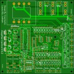
oh man that is a beauty of layout so "kawaii !" = lovely 😀
Regards
Juan
Thanks for the comment , I have to make some "modern" mackros (component
layout images) for all the 5/7.5/10/12/15/25mm components.
I DO like slightly larger pads ... Toner proofs especially (DIY etching is
less precise).
I'll look at some modern layouts for "fancy" screenprints. Once the initial
layout is done , a "pro" double sided layout is easy. I noticed only my
"spooky" was reconfigured from it's original form. The Kypton-V was a similar
hairpulling experience and I wanted a better design style (like JK's excellent
spooky rendition).
OS
If you look back a couple hundred pages in this thread there is a PDF description of the circuit.
This thread is too big !! 😱
post# or keyword ... please ?
Arduino - Calibration
Looks like simple coding to set analog limits to trigger CMOS outputs. 😎
ps - at least software is open source.
OS
The output circuits of the Arduino are digital in nature, but can be made more or less analog with integrators in the form of op amps. They can read temp to a .1 of a degree and measure high voltage with voltage dividers.
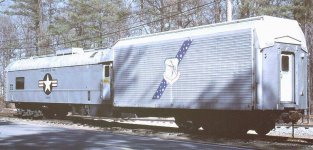
The Flight Simulators I worked on in the past were ALL analog computer types. Digital was in its infancy then. But today all Flight simulators are 100% digital, and a lot more precise.
This is what I worked on, a KC_135A flight simulator on a railroad car.
The Flight Simulators I worked on in the past were ALL analog computer types. Digital was in its infancy then. But today all Flight simulators are 100% digital, and a lot more precise.
This is what I worked on, a KC_135A flight simulator on a railroad car.
Attachments
Last edited:
Some of the Arduino pins can be analog, there is on board 10 bit ADC / DAC to allow for analog input and output.
Some of the Arduino pins can be analog, there is on board 10 bit ADC / DAC to allow for analog input and output.
Have started experimenting with them yet?
I found it.
Thanks Jeff, I was just about to drop the link 🙂
OS, if you'd like to have my firmware - just let me know where so send it 😉
Cheers,
Valery
Been playing about with some simple routines, I have yet to make a larger loop with conditional expressions and such. Very cool little device though.
I prefer analog "sensors", using Arduino just for management. This way the circuit stays fast enough. I also utilize hardware interrupts for key alerts (DC offset and over-current) and analog "acceleration" to make DC offset triggering even faster.
It's a pretty cool and very flexible board, I recommend it with no hesitation.
One may want to use the FET-based "electronic" relays, however I feel comfortable with good mechanical ones...
It's a pretty cool and very flexible board, I recommend it with no hesitation.
One may want to use the FET-based "electronic" relays, however I feel comfortable with good mechanical ones...
Krisfr,
I can't count the number of patterns I made for the KC-135. Hundreds of tools to make bonded panels for those planes.
I can't count the number of patterns I made for the KC-135. Hundreds of tools to make bonded panels for those planes.
... It's a pretty cool and very flexible board, I recommend it with no hesitation...
I've only recently ordered up some Chinese made Nano v3 boards and plan to begin learning them soon. What tool chain are you using?
I prefer analog "sensors", using Arduino just for management. This way the circuit stays fast enough. I also utilize hardware interrupts for key alerts (DC offset and over-current) and analog "acceleration" to make DC offset triggering even faster.
.
This likely keeps them from locking up as well.
I've only recently ordered up some Chinese made Nano v3 boards and plan to begin learning them soon. What tool chain are you using?
Hi Carl, you mean - for programming? I use just native Arduino environment. Available at arduino.cc
My firmware is organized in way that it's easy to add sensors / functions, adjust parameters (like delays, indication options), etc.
Cheers,
Valery
5.25" dia by 2.5" tall about 133mm by 63mm.Yes , that would do about >60-0-60Vdc .
My case is (W)300*(H)138*(L)360 mm (internal) . What are the trafo
dimensions ?
OS
Send me your address and it's yours.
Evan
This likely keeps them from locking up as well.
BTW, DC offset relay will go off in case of trouble even if Arduino fails completely (which is VERY unlikely, but still) 😉
Remember, it is designed by parachutist - we know what redundancy is about 😛 😀
Krisfr,
I can't count the number of patterns I made for the KC-135. Hundreds of tools to make bonded panels for those planes.
So you were a tool designer for Boeing ? The simulator I worked on was built by Erco.
Here is an excellent intro to Arduino on You Tube and pull you right in to let say doing a turn off circuit for a high temp on an output transistor emitter lead lets just say. I might include it on a board I am doing.
https://www.youtube.com/watch?v=EbaY5D0O9S0
It is a lot of fun and it is more in the area of expertise that my work career spanned. Main Frame computers with Emitter coupled logic, are far from Hawksford EC circuits, a long long way.
What heading or forum would a Arduino discussion be put under and should one be started?
Last edited:
An externally hosted image should be here but it was not working when we last tested it.
power up using 1kVA DIY transformer connected to a lamp tester. 😀
primary:
230v
secondaries:
53-43-0-43-53
18-0-18
- Home
- Amplifiers
- Solid State
- Slewmaster - CFA vs. VFA "Rumble"