If I am going to order a measurement mic (been meaning to get one for a while), what are your thoughts on UMIK-1 vs Dayton UMM-6? Parts express carries the Dayton, but I found another place in the US that carries the Umik (I don't want to wait for minidsp to ship it internationally)
They are probably comparable. I have the UMM-6 and really like it. I am surprised you don't have one all this time given your setups and experience with miniDSP. USB mics are great in that the preamp and ADC are all built in and in one unit so you don't have to calibrate a sound card or have to worry about noise pickup in the mic cable between mic and preamp. The measurements are automatically in actual absolute dB SPL as if you used a sound meter. The disadvantage is that it does not handle high SPL so if you want to do an actual measurement at 1 meter and 2.83v on some tapped horn designs with 108dB sensitivity it won't work as it will clip. You have to either get farther back or use less drive voltage and scale your answers to get the reference 1m and 2.83v value. Despite this limitation I find it invaluable for speaker design and building. Especially for dialing in XO's and EQ curves.
I finally have some time to take a look at AkAbak model of your tapped horn. Getting ready to pull all the dimensions of your drawings into a table.
I'm surprised I don't have one yet either. I've built several systems, but with each one I learn something new... Only really been at this for about 4 years. This project is making me feel like I'm really getting somewhere.
I have always just EQ'd to taste (by ear and with sine sweeps), but I am a classically trained musician with perfect pitch since I was about 10. My mom was a music and voice teacher (now retired). I've learned to trust my ear on everything- very in tune with it. However, I am ready to get real and do it the objective way this time. Absolutely.
Maybe I'll just order the Dayton, it's a bit cheaper. I haven't had the best of reaction times with minidsp support (laggy) and I don't want to hit any snafus with the calibration info requiring me to wait on them. Dayton it is.
And thanks again for the double threat double check. I feel like a kid in a classroom with dual professors 🙂 Not in a bad way though, because this is work I am proud of and I'm honored that you want to verify it for me!
Last edited:
Well, I can't argue with someone who was blessed with perfect pitch, i.e., a real-time FFT spectrum analyzer built into your ear and brain. 🙂 I am curious why you use Cinema 4D for your modeling and suspect that it may have something to do with your day job in the movie business? Anyhow, I use Solidworks and mechanical CAD programs may have an edge on dimensional accuracy because they depend on it for getting complex assemblies to fit together. These are indeed expensive packages though.
Ha! I never thought of perfect pitch as a realtime FFT. I'm going to use that 😉
You guessed correctly on the C4D usage. I do a lot of work for the broadcast and film industry.. Lots of logo animation and graphic treatments. That is my bread and butter.
But I also do tons of random fabrication- welding steel and sometimes doing woodwork. I started doing CAD several years ago with AutoCAD but switched to rhino and have never looked back. I want to learn the grasshopper plugin within it, I am positive it has special powers locked within it for designing TH's. Fabrication is not something I think I would ever want to make money off of, I do it for fun and for the benefit of me and my friends. Hence the speaker building 🙂
I just finished the model of your horn. One question: are you wiring the 4 ohm drivers in parallel for 2 ohm nominal load or in series for 8 ohm nominal load? Also, do you plan to use this from the back of your truck? If so, what is the height of the horn mouth centerline above the ground? It makes a difference for reflection/bounce calcs.
If I am going to order a measurement mic (been meaning to get one for a while), what are your thoughts on UMIK-1 vs Dayton UMM-6? Parts express carries the Dayton, but I found another place in the US that carries the Umik (I don't want to wait for minidsp to ship it internationally)
Check Cross Spectrum Labs, they offer the UMM and the UMIK professionally calibrated for a couple bucks more than you would pay buying them without pro calibration. The Dayton cal files measured by the manufacturer that come with the mic are notoriously incorrect. Not sure if they fixed that issue yet but probably not. At the price there's no reason not to get it from Cross Spectrum and be sure your cal is correct.
The UMM has a fragile neck. The issue is so bad Cross Spectrum won't even ship outside the US anymore due to failure rate.
All of these mics with built in preamp have a cheap preamp with a high noise floor so be aware of that. It's ok for measuring subs once in awhile but if you want more there's better tools for the job.
If you want less Dayton sells a tiny mic that plugs right into a phone for around $16 last time I checked. But then you can't run REW, you have to buy some sort of measurement package to run on your phone, and there's still the issue with Dayton's cal files.
When I get around to buying a mic it's probably going to be UMIK from CSL.
Last edited:
Akabak model of V2
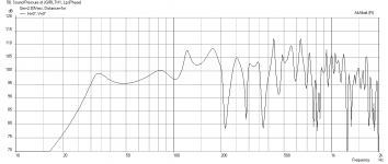
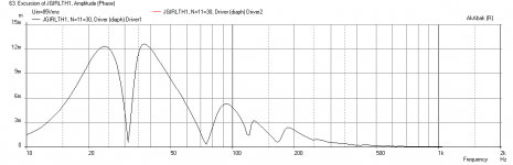
Here are the predicted results using a model in Akabak with geometry based on the dimensions provided. I am treating 90 deg turns as two-45 degree turns in order to fully account for the volume of the segment that is in the corners. I ended up with 24 waveguide element segments in the model and I am accounting for the inertia of the air passing through 90deg turns. No damping via stuffing has been applied. The expansion-contraction treatment of a 90 degree turn simulates an impedance change resulting from cross sectional area changes. The results are for the sub sitting on the floor in open space (2 pi steradians ) with mic at same level as centerline of horn mouth (5.4in). It matches the HR sims quite closely, the only thing I am noticing is that there appears to be a lot more HF leakage out of the horn mouth vs HR but that should not be a problem as you will be low-pass filtering it. The other thing I am noticing is the sag or saddle in the response at 50Hz is about 5dB and that is quite significant. I think the horn may have too much volume. You may be able to get away with a significantly narrower box (less than 37.5in width) and keep about the same SPL and reduce the sag. I will explore that later.
Here is the frequency response at 2.83v (wired in series for 8ohm nominal load):

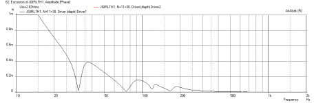
Here is the cone displacement at 2.83v running fullrange (no filters):

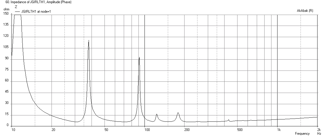
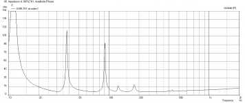
Here is the impedance:
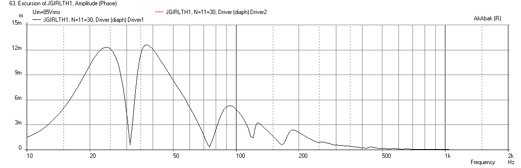
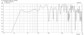
Here is the cone displacement with a 24Hz high pass (-24dB/oct) applied and 85volts to reach xmax of 12.5mm:
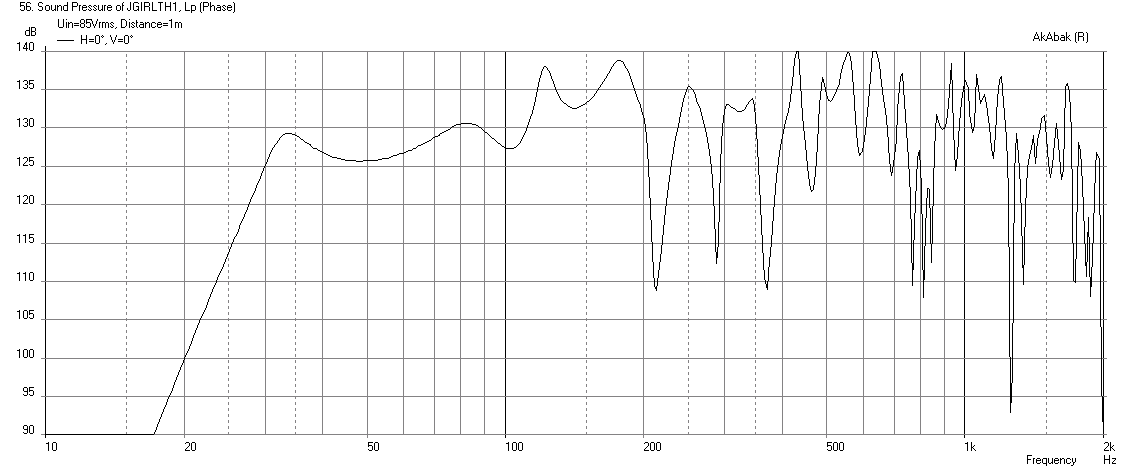
Here is corresponding max SPL at 85volts:
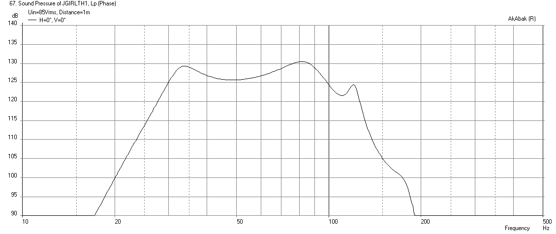
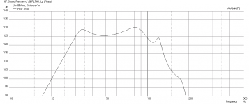
Applying a 48dB/oct LPF at 100Hz you get this:
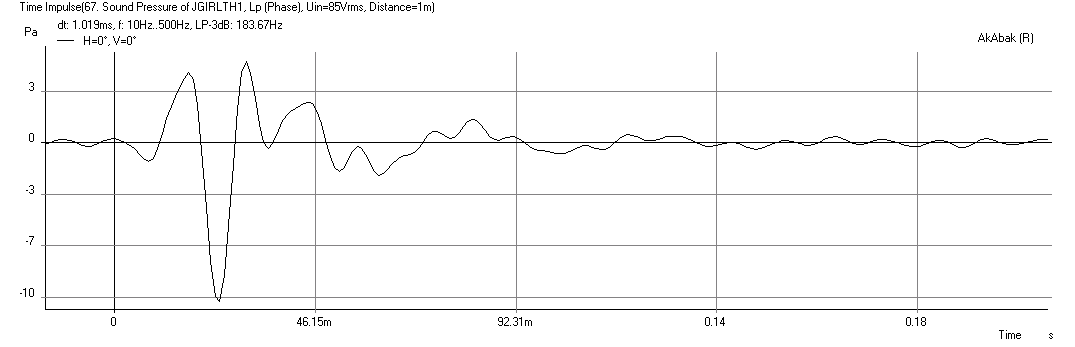
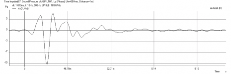
Looking at the Impulse Response on the HPF and LPF output there appears to be a negative maximal peak at 24ms delay. This would suggest flipping phase on drivers. That delay is long and may be result of the filters?
Here are the predicted results using a model in Akabak with geometry based on the dimensions provided. I am treating 90 deg turns as two-45 degree turns in order to fully account for the volume of the segment that is in the corners. I ended up with 24 waveguide element segments in the model and I am accounting for the inertia of the air passing through 90deg turns. No damping via stuffing has been applied. The expansion-contraction treatment of a 90 degree turn simulates an impedance change resulting from cross sectional area changes. The results are for the sub sitting on the floor in open space (2 pi steradians ) with mic at same level as centerline of horn mouth (5.4in). It matches the HR sims quite closely, the only thing I am noticing is that there appears to be a lot more HF leakage out of the horn mouth vs HR but that should not be a problem as you will be low-pass filtering it. The other thing I am noticing is the sag or saddle in the response at 50Hz is about 5dB and that is quite significant. I think the horn may have too much volume. You may be able to get away with a significantly narrower box (less than 37.5in width) and keep about the same SPL and reduce the sag. I will explore that later.
Here is the frequency response at 2.83v (wired in series for 8ohm nominal load):
Here is the cone displacement at 2.83v running fullrange (no filters):
Here is the impedance:
Here is the cone displacement with a 24Hz high pass (-24dB/oct) applied and 85volts to reach xmax of 12.5mm:
Here is corresponding max SPL at 85volts:
Applying a 48dB/oct LPF at 100Hz you get this:
Looking at the Impulse Response on the HPF and LPF output there appears to be a negative maximal peak at 24ms delay. This would suggest flipping phase on drivers. That delay is long and may be result of the filters?
Attachments
-
 Jgirlth1-freq-1m-2.83v.png36.7 KB · Views: 280
 -
 Jgirlth1-freq-1m-Displ.png24.3 KB · Views: 276
 -
 Jgirlth1-freq-1m-Impedance.png31.7 KB · Views: 279
 -
 Jgirlth1-freq-1m-Displ-at-xmax-HPF.png24.4 KB · Views: 279
 -
 Jgirlth1-freq-1m.png36.4 KB · Views: 276
 -
 Jgirlth1-freq-1m-max-SPL-HPF-LPF.png29 KB · Views: 268
 -
 Jgirlth1-Impulse.png11.5 KB · Views: 541
Last edited:
Check Cross Spectrum Labs, they offer the UMM and the UMIK professionally calibrated for a couple bucks more than you would pay buying them without pro calibration. The Dayton cal files measured by the manufacturer that come with the mic are notoriously incorrect. Not sure if they fixed that issue yet but probably not. At the price there's no reason not to get it from Cross Spectrum and be sure your cal is correct.
Not sure how notorious it is because this is first I have heard of this problem of bad cal files. You can see the cal line in REW, it is no more than about 1dB on the extremes. The data I have measured on drivers matches factory response plots very well. These mics probably all use something similar to the Panasonic WM-61A capsules which are essentially flat from
The factory within 1dB. In my case I have not seen an issue with calibrations being off. Although for $95 vs $80 that is a good value to get a calibration file from 5Hz to 25kHz.
http://cross-spectrum.com/measurement/calibrated_umm6.html
Last edited:
Accuracy check details -
Total flare length is very accurate. In the plans it's .33 cm longer than the sim. I'm not sure what was going on in post 175 but whatever you are doing gives great results.
Cross sectional areas are all within about 2.25 percent error or less, sometimes a lot less. That's pretty good, probably better than most people and the methods they use are able to achieve. Definitely not perfect but not bad.
The first thing I did was cut the plans into 13 segments.
Then I took the measurements in post 182, did all the metric conversions, calculated the cross sectional areas at each of the 14 segment markers, and calculated the lengths between each segment. Then I compared them to what the Hornresp Horn data file said they should be and calculated the percentage of error.
Probably should have made a spreadsheet for that but initially I was only planning to check a few points and I ended up doing all the important spots.
The vast majority of error occurs in the first part of the flare between the red lines marked S1 - S4 in the picture above, with the highest percentage of error being over 2 percent at S4. The last part of the horn, from S7 to the end is considerably more accurate, with percentage of error of less than 1 percent.
In the plans S1 is too big and at S4 it's too small so it would look something like the following picture with the black line being the Hornresp sim and the grey line being the actual measurement from the plans. (Straightened and exaggerated to show the error trend.)
Over this result is not bad. Not perfect but not far off.
NOTE - ironically my accuracy check isn't perfectly accurate, there is a small percentage of error due to the fact that the highest resolution I could get in the Hornresp Horn Data file was a sample at every .3 cm and I had to chose the nearest sample to compare to the segment marker locations in the plans. This could result in as much as .1 or so percent error in each segment marker CSA. I could have been more accurate by drawing and measuring the Data File flare and the flare in the plans in Sketchup but I didn't want to get into that. There's also the rounding issue, measurements in the plans are imperial and rounded to two decimal places so there's a potential for error there too but there's nothing I can do about that.
Total flare length is very accurate. In the plans it's .33 cm longer than the sim. I'm not sure what was going on in post 175 but whatever you are doing gives great results.
Cross sectional areas are all within about 2.25 percent error or less, sometimes a lot less. That's pretty good, probably better than most people and the methods they use are able to achieve. Definitely not perfect but not bad.
The first thing I did was cut the plans into 13 segments.
An externally hosted image should be here but it was not working when we last tested it.
Then I took the measurements in post 182, did all the metric conversions, calculated the cross sectional areas at each of the 14 segment markers, and calculated the lengths between each segment. Then I compared them to what the Hornresp Horn data file said they should be and calculated the percentage of error.
An externally hosted image should be here but it was not working when we last tested it.
Probably should have made a spreadsheet for that but initially I was only planning to check a few points and I ended up doing all the important spots.
The vast majority of error occurs in the first part of the flare between the red lines marked S1 - S4 in the picture above, with the highest percentage of error being over 2 percent at S4. The last part of the horn, from S7 to the end is considerably more accurate, with percentage of error of less than 1 percent.
In the plans S1 is too big and at S4 it's too small so it would look something like the following picture with the black line being the Hornresp sim and the grey line being the actual measurement from the plans. (Straightened and exaggerated to show the error trend.)
An externally hosted image should be here but it was not working when we last tested it.
Over this result is not bad. Not perfect but not far off.
NOTE - ironically my accuracy check isn't perfectly accurate, there is a small percentage of error due to the fact that the highest resolution I could get in the Hornresp Horn Data file was a sample at every .3 cm and I had to chose the nearest sample to compare to the segment marker locations in the plans. This could result in as much as .1 or so percent error in each segment marker CSA. I could have been more accurate by drawing and measuring the Data File flare and the flare in the plans in Sketchup but I didn't want to get into that. There's also the rounding issue, measurements in the plans are imperial and rounded to two decimal places so there's a potential for error there too but there's nothing I can do about that.
Not sure how notorious it is because this is first I have heard of this problem of bad cal files.
I've heard of a bunch. Here's one showing EMM measurements and a bunch of people also respond saying their manufacturer CAL files are junk, described as "night and day" difference between the manufacturer CAL and the CSL pro calibration file - Dayton EMM-6 vs Cross Spectrum EMM-6
Here's one for the IMM - Dayton iMM-6 - measurement progress
This one is interesting because it shows that the Dayton CAL file is actually worse than not using a CAL file at all.
I don't have one the UMM right now but you get the point. Search the parts express forum and you will find more of these.
None of this matters much for subwoofers, but it starts to matter at 1khz and up.
Glad to hear it is checking out well! Mainly because I just finished cutting 😀

I'll keep you updated as the build progresses. I skipped out on a DJ gig at a friend's house party tonight to make progress.. Kind of not in a party mood anyway, though... Assembling this has me dreaming of future parties!
I'll keep you updated as the build progresses. I skipped out on a DJ gig at a friend's house party tonight to make progress.. Kind of not in a party mood anyway, though... Assembling this has me dreaming of future parties!
I have 35mm diameter dowels for bracing, do you think that will be ideal or should I go with a smaller diameter? They looked nice and beefy.
Hey you work fast - I like that. 35mm dowels are fine as long as you use them close together enough and secure them with screws in addition to glue as the dowels need to contain tension stress in addition to compression. I worry about a butt joint on the dowel coming apart with glue only from the outward pressure exerted on the horn walls. Don't know if you saw my sims earlier but had a question about why you are going with 37.5in internal width. You could go with 32 in width and reduce volume which saves weight and allows a higher max SPL as excursion is reduced. But too late as you have already cut wood.
Sketch of layout and dims used on Akabak model
Here are the photos of the layout and dimensions that I used for the akabak model.
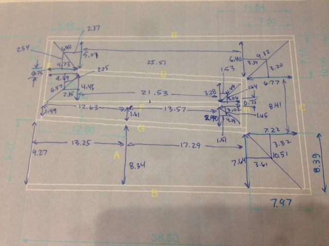
Here are the dimensions in a tabular form from the diagram above:
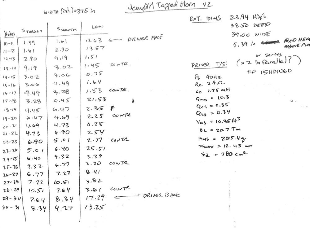
Here are the photos of the layout and dimensions that I used for the akabak model.
Here are the dimensions in a tabular form from the diagram above:
Code:
| #### DEFINE WAVEGUIDE GEOMETRY ####
| Define Horn Segments (need to multiply by Width for area): S_Throat, S_Mouth, Length
| Note that waveguides have to expand, for contractions, reverse nodes

	S10T=1.49*0.0254; S10M=1.61*0.0254; L10=12.63*0.0254;  | Closed end stub to driver1 and 2
	S11T=1.61*0.0254; S11M=2.90*0.0254; L11=13.57*0.0254;  | driver1 and 2 to first turn
	S12T=2.90*0.0254; S12M=4.19*0.0254; L12=1.51*0.0254;   | 45 deg expansion
	S13T=3.02*0.0254; S13M=4.19*0.0254; L13=1.45*0.0254;   | 45 deg contraction (reverse nodes)
	S14T=3.02*0.0254; S14M=3.06*0.0254; L14=0.75*0.0254;   |
	S15T=3.06*0.0254; S15M=4.49*0.0254; L15=1.64*0.0254;   | 45 deg expansion
	S16T=3.08*0.0254; S16M=4.49*0.0254; L16=1.53*0.0254;   | 45 deg contraction (reverse nodes)
	S17T=3.28*0.0254; S17M=4.45*0.0254; L17=21.53*0.0254;  | first long horizontal stretch to left
        S18T=4.45*0.0254; S18M=6.47*0.0254; L18=2.35*0.0254;   | 45 deg expansion
        S19T=4.69*0.0254; S19M=6.47*0.0254; L19=2.25*0.0254;   | 45 deg contgraction (reverse nodes)
        S20T=4.69*0.0254; S20M=4.74*0.0254; L20=0.75*0.0254;   |
        S21T=4.73*0.0254; S21M=6.90*0.0254; L21=2.54*0.0254;   | 45 deg expansion
        S22T=5.01*0.0254; S22M=6.90*0.0254; L22=2.37*0.0254;   | 45 deg contraction (reverse nodes)
        S23T=5.01*0.0254; S23M=6.40*0.0254; L23=25.51*0.0254;  | 2nd long horiz stretch to right
        S24T=6.40*0.0254; S24M=9.32*0.0254; L24=3.39*0.0254;   | 45 deg expansion (turn down in upper back corner)
        S25T=6.77*0.0254; S25M=9.32*0.0254; L25=3.20*0.0254;   | 45 deg contraction (reverse nodes)
        S26T=6.77*0.0254; S26M=7.22*0.0254; L26=8.41*0.0254;   | long stretch down in back
        S27T=7.22*0.0254; S27M=10.51*0.0254; L27=3.82*0.0254;  | 45 deg expansion (turn left in lower back corner)
        S28T=7.64*0.0254; S28M=10.51*0.0254; L28=3.61*0.0254;  | 45 deg contraction (reverse nodes)
        S29T=7.64*0.0254; S29M=8.34*0.0254; L29=17.29*0.0254;  | from turn to driver backs at tap location
        S30T=8.34*0.0254; S30M=9.27*0.0254; L30=13.25*0.0254;  | from driver backs to mouth exit plane
Attachments

Last edited:
Wow!! Truly devotion, I freaking love it. Thanks to both of you for verifying my design- it's really neat that you've gone to such measures (oops another pun, ha!)
I did think about the fact that I could go with a smaller width.. In fact one could even divide internal width in half and run a single driver. I could have definitely shaved a few inches off, but not too much as there would barely be any room to brace in between the drivers.
Cutting the pieces has really shown me how truly compact the box is, I am actually kind of surprised for some reason. This will be one heck of a speaker for such small size. Divided in half with 1 driver, it is very very compact!
I am now done drawing out the plans onto the side pieces, I am ready to start gluing and screwing!

I have done test fits with all of the pieces, and I went overboard on the precision. Everything is lining up perfectly, right on the money. I always say most of the work is in the prep, and makes assembling it a lot easier... and plus I'll just feel that much better once it is done 🙂
I did think about the fact that I could go with a smaller width.. In fact one could even divide internal width in half and run a single driver. I could have definitely shaved a few inches off, but not too much as there would barely be any room to brace in between the drivers.
Cutting the pieces has really shown me how truly compact the box is, I am actually kind of surprised for some reason. This will be one heck of a speaker for such small size. Divided in half with 1 driver, it is very very compact!
I am now done drawing out the plans onto the side pieces, I am ready to start gluing and screwing!
I have done test fits with all of the pieces, and I went overboard on the precision. Everything is lining up perfectly, right on the money. I always say most of the work is in the prep, and makes assembling it a lot easier... and plus I'll just feel that much better once it is done 🙂
I forgot to ask.. How close together should I fasten the dowels? It is going to be mega tricky screwing them in so I was thinking I might use some of my west systems epoxy which soaks into the wood. I could also line up the dowels so that they are aligned on either side of the panels, they would support each other in kind of a lattice of sorts.. Dunno if that makes sense.. Let me draw a pic

- Home
- Loudspeakers
- Subwoofers
- FaitalPRO 15HP1060 vs 3015LF for tapped horn?