woofertester, try to power those ebay kits with well regulated external power supply, even the kit has rectifier and filtration capacitors on the board and only needs AC...I had luck with problematic current amp kits to tame them this way
Have you looked at the output on an oscilloscope for all frequencies?
Which kit did you get to work?
What ebay kits are you referring to?
All of them!
This one is on my bench right now. Horrible crossover distortion at 20 Hz.
TDA7294 DC Servo Current Stereo Amplifier Board 100W ±30V?±35V NE5532N | eBay
Good point. Realistically, the largest currents are at low frequency where d/dt is small. Where d/dt is large, at high frequencies, currents are small.
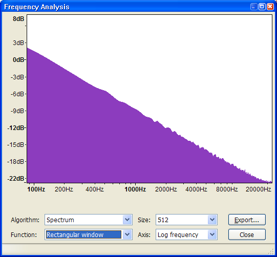
If you take an FFT of an entire song, you get the power envelope. This envelope for most music looks like pink noise:
Sure, di/dt may even be constant with freq. that dosnt mean it won't be a problem. It depends on L and R. It will be easy enough to see if your output voltage hits the rails when your system is up and running. I'm very curious to see.
I have a 200W amp that I had built for me. It is too expensive to be commercial. I use it to make difficult speakers reach Xmax at Fs. This amp clips easily at high frequencies driving a normal speaker with no zobel. Impedance flattening would be required to use of this kind of amp for music with a naked driver.Sure, di/dt may even be constant with freq. that dosnt mean it won't be a problem. It depends on L and R. It will be easy enough to see if your output voltage hits the rails when your system is up and running. I'm very curious to see.
I don't see your point. I'm talking about voltage overhead for current driving speakers.
I think clipping is a bigger problem than voltage overhead. I would have to see some calculations or a capture of the voltage overhead problem. I have seen the clipping problem with a real speaker.
We're saying the same thing. But voltage clipping in current drive may be caused by L di/dt before you run out of power. Again, think about voltage driving a capacitive load. If your signal drops quickly to zero the current thru the cap will be huge. It's like shorting out a capacitor. Same thing with current driving an inductor, only the voltage will be huge.
Perhaps class G would be the way to go. Extra voltage when needed without higher idle dissipation. Class-G Amplifiers
Have you looked at the output on an oscilloscope for all frequencies?
Which kit did you get to work?
this kit...
JFET 2SK30A FET Buffer LM1875 Amplifier Board 15V?20V Excluding Radiators | eBay
no, I have not looked at oscilloscope, I am only using tranconductance amp for mid-tweet section in biamplified system, and it sounds great
this kit...
JFET 2SK30A FET Buffer LM1875 Amplifier Board 15V?20V Excluding Radiators | eBay
no, I have not looked at oscilloscope, I am only using tranconductance amp for mid-tweet section in biamplified system, and it sounds great
Thank you for the reply.
Do you have a schematic for this kit? How do you verify that it is a tranconductance amp?
The kit on my bench works at 500 Hz, however, the shape of the output sine wave is visibly distorted. The wave form looks like it is melting to the side.
At 20 Hz, crossover distortion is horrible.
I am powering the kit with two 30V 5A regulated power supplies.
Thank you for the information. I had a look at the kit. No schematic to be found which is typical for a lot of Chinese kits.no, I do not have schematics, but it has this output stage plus DC servo
The servo is needed if there is no +/- offset control. Also there is no compensation. Most working designs like this have HF compensation to eliminate oscillations.
The Lm1875 is internally compensated when used at a gain of 10 or more. That circuit should be ok down to about 3 ohms before additional compensation. This doesn't mean that there shouldn't be an rf filter at the input.
no, I do not have schematics, but it has this output stage plus DC servo
Hello adason
I have ordered one of these LM1875 kits to try out.
There are a bunch of FETS and an op amp as well as the LM1875. I assume that the op amp is the DC servo. Any idea what the FETs are doing?
If it works, I would disable the servo and try to add the circuitry to adjust the DC offset to zero. I want to be DC coupled with gain.
Is there still no descent ready made kit for current drive, on ebay or elsewhere?
I would use it on a sealed mid in the 200-2kHz range (active crossover and EQ), so no problem with distortion down low or oscillation up high...
I would use it on a sealed mid in the 200-2kHz range (active crossover and EQ), so no problem with distortion down low or oscillation up high...
The fets appear to be an input buffer. Not really needed but they probably add a little "flavor" to the sound.
Is there still no descent ready made kit for current drive, on ebay or elsewhere?
I would use it on a sealed mid in the 200-2kHz range (active crossover and EQ), so no problem with distortion down low or oscillation up high...
None that I have tested. I hook them up to an oscilloscope and look for noise, oscillations and waveform distortion.
Maybe I should start a thread of eBay current source kits.
It looks like transconductanc , the feedback is coming from the current going thru r7. Since it's a transconductance Amp the voltage out will look funny, (Distorted) but that dosen't matter, it's the curent (out) thru the speAker that should be the same as the input signal. Thus transconductance. I out= A Vin. Scope the voltag at r7.
- Home
- Amplifiers
- Solid State
- Current drive for Loudspeakers