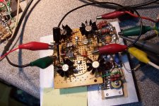
It is mains-powered in fact, mainly because of the power-hungry MAN's-display, but it could as well be battery operated without changing the functionMystery device:
With battery power and a touch pad, it probably compares a human, assumed as 0v to *something else* and discovers the differential (and also the location)?
No, and noA tracer? A bug sweeper?
Apparently, the opamps are not in the signal path, they control bias voltages, and flipping them would result in latchup.Instable device:
Flip the op amp to inverting? That's my only guess. Starting with an op-amp and then following it with a complexity doesn't make sense visually. Generally speaking, op-amps are for shortcuts and that one sure didn't. Is it a nesting arrangement or howland?
The amp itself seems to be only inverting
Could it be a frequency counter probe? Magnetic field probe? Something to check the voltage between user and probe to detect danger?
Not exactly spot on, but almost: just an integration awayCould it be a frequency counter probe?
No, just look closer and think about itMagnetic field probe? Something to check the voltage between user and probe to detect danger?
Hint: It is useful for certain fields of electronics, but also for mechanics (and maybe others, weavers perhaps?)
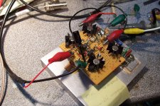
Yet another "fossil": this one is labelled "stabilité marginale", and that is indeed the case: when loaded with 3 ohm, part of the lower half-wave is festooned with VHF oscillation.
Easy to fix apparently: I probably didn't try hard enough the last time, an additional comp cap does the trick.
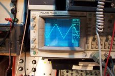
This one is really wideband: it uses paralleled BDX37's as OP, and it does give results: see the oscillogram (it is a 200KHz triangle, and the apparent defects near the top are not caused by the amp), measured on a 3 ohm load
Easy to fix apparently: I probably didn't try hard enough the last time, an additional comp cap does the trick.
This one is really wideband: it uses paralleled BDX37's as OP, and it does give results: see the oscillogram (it is a 200KHz triangle, and the apparent defects near the top are not caused by the amp), measured on a 3 ohm load
Attachments
I rarely give my "proofs of concepts" the opportunity to fry a speaker's voice coil.... . . but how does it do with a speaker?
This one is no exception
What procedure do you go through to ensure it won't, if you intend to use the circuit for that purpose?
When eventually I decide to go further with a prototype, I make additional tests and checks, to make sure it is well-behaved and idiot-proof in every conceivable circumstance.What procedure do you go through to ensure it won't, if you intend to use the circuit for that purpose?
Otherwise, I simply limit myself to performance tests.
I just use this thang. I added a 4.7uF little green Nichicon ES bypass cap over that thing to pass the hf around it. Anyway, that outfit goes series to the speaker (series to groundside, speaker return, if a split rail amp). Its really good for a test speaker. Can put it at the speaker cabinet so that the amp is driving first the cable.
Last edited:
Yes, it is a good idea to "formalize" such a device.
I sometimes use a flying cap for a test, but then I have to care about polarity (in some cases), or find a second one, all this discourages use.
When you have a neat little thing always ready, that makes things easier.
I will probably build a pair of them in the coming days.
I sometimes use a flying cap for a test, but then I have to care about polarity (in some cases), or find a second one, all this discourages use.
When you have a neat little thing always ready, that makes things easier.
I will probably build a pair of them in the coming days.
By default, I build all my test prototypes as DC-coupled, x11 (or x-10) gain blocks, which means they already have the maximum bass extension possibleI wonder if you'll get a bass extension from the speaker.
Your statement is true at the amplifier; however. . .By default, I build all my test prototypes as DC-coupled, x11 (or x-10) gain blocks, which means they already have the maximum bass extension possible
During the loss of an output cap at a certain bass frequency, whereupon if one is a bit lucky (or stubborn, preferably both) for choosing the capacitance value, and before the loss becomes too severe, the electronic dampening of the woofer will become slightly looser, as if in a larger cabinet, so you can get more bass extension with an ac coupled woofer (when if the cap size is fortunate for a given speaker).
For me, it is typical that the capacitance value is sized for that particular purpose, and in every case it was done for practical benefit of greater bass extension. I have not yet witnessed any exceptions. It worked every time.
- Status
- Not open for further replies.
- Home
- Amplifiers
- Solid State
- A dive into the past