[WRT load invariance and a resistive load] I think the choice of where to correct the problem (ie, at the load or through feedback... even assuming the amp choice is fixed) outweighs passive component concerns. Doing it this way is going to expose the issue (if there is an issue), to the amplifier's load varying qualitiesCrossover, phase adjustments (delay), response compensation and all that stuff should be done digitally (or analog at line level) where it belongs, not with big coils of wire and foil stuffed into some speaker box where it can only foul things up.
Last edited:
How much does that affect the frequency response of usual speakers?
Not much.
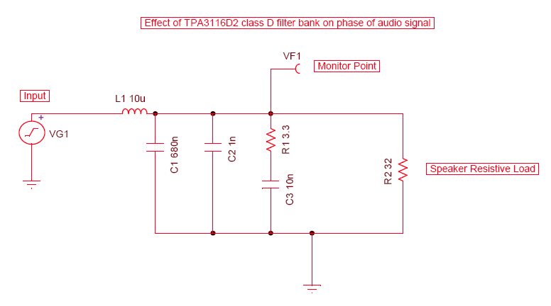
I have looked at this and sim'd the circuit of the output filter and a resistive load in spice. The inductor used by the 3116 is 10 to 22 micro Henry - the response filters stuff above 41khz below that it is flat. The impedance of load can vary but the transfer function of the output LC filter never digs into the sub 20khz range. Note that inductances of crossovers are typically in milli Henry range.
Note that with 3116 it is possible to change the default carrier freq from 400kHz up to 1.2MHz (variable in discrete steps). Possible to use even smaller inductors and even a ferrite bead.
Last edited:
Power response can be straight regardless of lobing ...
Well that is simply not true.
And if I ask why it can't be straight, the answer would be: 0.1 dB variations is not straight. I'm done with this B.S.
I'm done with this B.S.
That's good, I'm tired of it too.
How can a response hole not lower the power response?
See attached FR plot vs load for a small commercial Class-D amp, based on some TDA749x (ST Micro) chip.How much does that affect the frequency response of usual speakers?
Only with proper resistive load (at about 5R in this case) a flat response is achieved, using a Butterworth characteristic. Too much or too little damping result in a drooping or peaking top end like one has to expect from a L-C tank circuit.
The level changes from voltage drop accross the inductor is rather benign in comparsion.
Attachments

How can a response hole not lower the power response?
OM*G, it can't be that difficult to calculate distances and wave lengths 🙂
A simple puzzle to start the brain: 1st generation imperfect prototype of KS-1807, MTM section with 2x5.25" mids + ribbon tweeter crossed @ ~4 kHz. Almost "optimal" power response is achieved regardless of obvious and strong vertical lobing. Blue=power, Red=DI:
An externally hosted image should be here but it was not working when we last tested it.
Power response curve is just approximation based on 36 hor + 36 ver measurements - not the holy truth, but significant holes would be visible if they exist. $10k question is why?

Last edited:
See attached FR plot vs load for a small commercial Class-D amp, based on some TDA749x (ST Micro) chip.
Only with proper resistive load (at about 5R in this case) a flat response is achieved, using a Butterworth characteristic. Too much or too little damping result in a drooping or peaking top end like one has to expect from a L-C tank circuit.
The level changes from voltage drop accross the inductor is rather benign in comparsion.
Well, this is a completely different class D amp as the 3116 is the latest gen from TI.
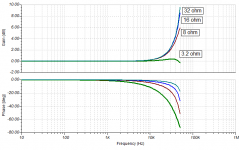
Here is a SPICE sim of the output factory specified output LC filter on the gain and phase for different loads ranging from 3.2ohm (design load), up to 32ohms. Note that the gain at 20kHz is 1dB or less. The phase effects below 10kHz are below 10deg.

Attachments

Almost "optimal" power response is achieved regardless of obvious and strong vertical lobing.
An "optimal" power response IMHO would be one where the DI was flat. The steep rise of the DI as shown indicates non-constant directivity - if one cares about that sort of thing.
There is no "lobbing" in that design, only strong beaming- a different sort of problem. That's why you don't see any crossover effect on the power response. That system is "co-axial" in my book and I agreed that we would not see any effect on the power response at crossover.
There is no "lobbing" in that design, only strong beaming- a different sort of problem. That's why you don't see any crossover effect on the power response. That system is "co-axial" in my book and I agreed that we would not see any effect on the power response at crossover.
How can you consider an MTM section, with a driver separation of probably around 8" between the two Ms and crossed at 4kHz, anything remotely close to being coaxial?
In the vertical axis you're going to get terrible lobing. MTMs are typically known for this, especially ones with high xover points. The only way to get around this would be to cross over at at least 1/2 the wavelength of the path separation between the two Ms.
I don't think so: all these % and db figures are matching the 25uV residual noise measurement, and I guess this one is easy to make correctly.
Indeed, you are correct I was ignoring the amplifiers own inherent noise. I figured it would be a bit lower than that.
How can you consider an MTM section, with a driver separation of probably around 8" between the two Ms and crossed at 4kHz, anything remotely close to being coaxial?
To me, two drivers operating over the same bandwidth are a single source. The center of this source is at the exact same location as the Tweeter, hence coaxial. There need not be any "lobbing" in this configuration, i.e. no cancellation off axis because of non-coincident sources. The two LF drivers separated by 8" will yield a very narrow vertical directivity, but this is not "lobbing" from non-coincidence. At least that's the way I view the situation. That is the way it would be modeled.
Maybe we should consider a different set of terms for the cancellation due to non-coincidence and lobbing caused by the finite size of a source. o me these things are quite different, but yet we seem to be using the same term for both of them.
Last edited:
To me, two drivers operating over the same bandwidth are a single source. The center of this source is at the exact same location as the Tweeter, hence coaxial.
They only approach a single source though if the wavelength is large compared to the driver separation. If not they should be viewed as two individual sources.
There need not be any "lobbing" in this configuration, i.e. no cancellation off axis because of non-coincident sources.
Well there's the problem, they aren't coincident above around 1000Hz, so you're going to get comb filtering/lobing occurring as you go up and down in the vertical plane.
When you add in the tweeter you're going to get even more issues created as it goes in and out of phase with each driver as you sweep through the vertical angles.
This is one of the reasons why MTMs aren't supposed to be used unless you can cross at a suitable frequency, that minimises the non coincident nature of the two midbass drive units, at higher frequencies.
Maybe we should consider a different set of terms for the cancellation due to non-coincidence and lobbing caused by the finite size of a source. o me these things are quite different, but yet we seem to be using the same term for both of them.
So you're looking at lobing purely from the point of view of a drivers inherent off axis response that would lead to a certain directivity profile?
Lobing is traditionally used, with standard loudspeaker design, to define the regions where two (or more) non coincident drivers go in and out of phase with one another as you sweep through the vertical axis (or horizontal axis if the drivers are mounted that way too). A polar plot, done at as specific frequency (usually the xover frequency), is usually the best way to view these as the graphical representation actually looks like 'lobes' that show regions of high and low intensity versus angle.
I guess that with a standard loudspeaker, when looking at the horizontal axis, you could use a polar plot and lobing to display what the directivity of a loudspeaker is typically like, but this isn't often done. Probably because most of them follow (to differing amounts) the wide/narrow/wide pattern, where in these designs the only interesting part about the polar plots is to see how friendly a design is towards listening above, or below the standard listening axis.
In the vertical axis you're going to get terrible lobing. MTMs are typically known for this, especially ones with high xover points. s.
Poorly executed MTMs fit your generalization, well designed not so much. Remember the narrow vertical directivity of a ribbon is very much a friend in such a design. IMO such an arrangement will outperform any current coax on treble smoothness alone. But I would concede this is not a nearfield speaker either and since I don't listen in the nearfield not a major concern where vertical lobing is concerned. I generally stay seated when enjoying music.
Poorly executed MTMs fit your generalization, well designed not so much.
My comment was made towards kimmosto's MTM crossed at 4kHz. Whatever the tweeter may do in that situation, you're going to get vertical lobing from the separation of the mid drivers. Maybe this is wanted in some peoples eyes as it does create nulls in the vertical off axis and limits the sound thrown out to the floor and the ceiling.
Agreed that 8" C2C is a bit more than I'd care to chew unless the listening distance were 3m or more
An "optimal" power response IMHO would be one where the DI was flat. The steep rise of the DI as shown indicates non-constant directivity - if one cares about that sort of thing.
I'm aware that corner of DI is too sharp. Reason is that it was mechanically too easy and tempting to make prototype with 45 deg bevels, which moved resistance ports a bit too far. But this will be improved in the next version. Correction will not produce flat DI which is not right, producing too soft and death sound when directivity is not very strong. Shape will be like with very small 2-way which is closer to important/significant real world sound sources.
Should remember that measurement is from MTM section only - not complete speaker, and overall shape of DI was not the topic here.
There is no "lobbing" in that design, only strong beaming- a different sort of problem. That's why you don't see any crossover effect on the power response.
M-M is lobing(/comb filtering) and MM-T is lobing. Beaming too, of course, but both no problem in the spot.
Last edited:
IMO such an arrangement will outperform any current coax on treble smoothness alone.
Correct. Those MTM prototypes with single cardioid bass units were compared to 205/2, and result was clear; just "very good coaxial" is not capable to beat well designed lobing speaker. Coincidence gives coherence and easiness for casual listening which is not always enough for everybody.
See attached FR plot vs load for a small commercial Class-D amp, based on some TDA749x (ST Micro) chip.
Only with proper resistive load (at about 5R in this case) a flat response is achieved, using a Butterworth characteristic. Too much or too little damping result in a drooping or peaking top end like one has to expect from a L-C tank circuit.
The level changes from voltage drop accross the inductor is rather benign in comparsion.
How does that translate into magnitude response distortion? xrk971's data suggests the error is <1dB?
- Status
- Not open for further replies.
- Home
- Loudspeakers
- Multi-Way
- Why crossover in the 1-4khz range?