Test #1
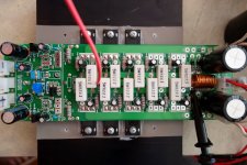
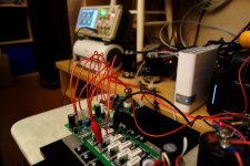
OK, guys, here is the first configuration. No buffers - 3 pairs of MOSFETs are connected directly to the front-end (cascoded VAS, running at 4.7 mA). No additional compensation. Only 3 pairs of MOSFETS and a spreader (plus 2 Zeners to protect the FETS).
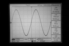
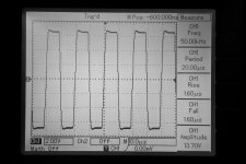
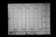
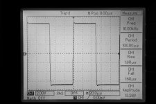
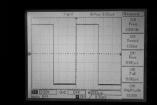
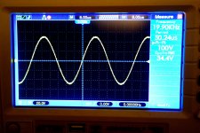
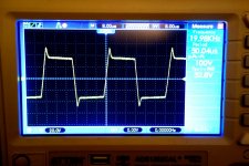
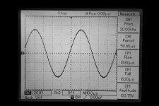
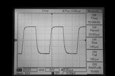
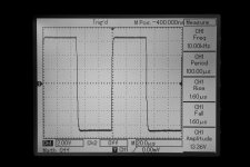
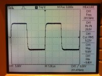
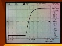
70mA per pair idle current. See some curves (Bode, 1KHz, 10KHz, 20KHz, 50 KHz squares, etc.). Rise/fall times are limited by the front-end compensation (I did not touch it since I used it with the previous setup - SleaMaster with BJTs).
Unfortunately, I can't see the spectrums - something happened to my soundcard's outputs - they stopped working. Spent 2 hours trying to figure out what happened, but looks like a hardware failure 🙁
Sounds very good - maybe a bit warmer that BJT version. Need more listening to say something more specific.
The good thing - it works flawlessly.
Anyway, I'll try the second configuration - with single EF buffer running at 10-11mA - today in the evening.
Ranchu - [HERE] is what I drive it with.
I will post the "final" OPS schematic later, probably today...
OK, guys, here is the first configuration. No buffers - 3 pairs of MOSFETs are connected directly to the front-end (cascoded VAS, running at 4.7 mA). No additional compensation. Only 3 pairs of MOSFETS and a spreader (plus 2 Zeners to protect the FETS).
70mA per pair idle current. See some curves (Bode, 1KHz, 10KHz, 20KHz, 50 KHz squares, etc.). Rise/fall times are limited by the front-end compensation (I did not touch it since I used it with the previous setup - SleaMaster with BJTs).
Unfortunately, I can't see the spectrums - something happened to my soundcard's outputs - they stopped working. Spent 2 hours trying to figure out what happened, but looks like a hardware failure 🙁
Sounds very good - maybe a bit warmer that BJT version. Need more listening to say something more specific.
The good thing - it works flawlessly.
Anyway, I'll try the second configuration - with single EF buffer running at 10-11mA - today in the evening.
Ranchu - [HERE] is what I drive it with.
I will post the "final" OPS schematic later, probably today...
Attachments
You work super fast Valery!
I'm amazed that you can drive three pairs directly from the VAS. How much VAS current are you running? Seems to be stable with just gate stoppers and no gate-drain zobels - I'm impressed.
Great work 🙂
I'm amazed that you can drive three pairs directly from the VAS. How much VAS current are you running? Seems to be stable with just gate stoppers and no gate-drain zobels - I'm impressed.
Great work 🙂
You work super fast Valery!
I'm amazed that you can drive three pairs directly from the VAS. How much VAS current are you running? Seems to be stable with just gate stoppers and no gate-drain zobels - I'm impressed.
Great work 🙂
Thank you 🙂 Really interesting theme 😉
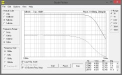
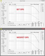
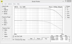
VAS (and therefore cascode) runs at 4.7 mA. My initial simulation showed no problem at, let say, 1 KHz, but certain THD increase closer to 20KHz. That's actually why I am going to test an option with additional EF buffer in front of MOSFETs. Unfortunately I can't measure THD now because my sound-card got broken, but looking at the Bode plots, I see that MOSFETs definitely give additional load to cascode at HF (see the picture attached).
And yes, I really like it works with no additional caps. Gate stoppers are 220 ohm (rather usual value)...
Attachments
You beat me to it! Though I'm going to use the EF buffer from the start...
I will most likely stay with the buffer as well, but I could not refuse from trying the simplest configuration first 🙂 Now we'll be able to really compare...
This is pretty cool though. Same board with minor changes in values and you have a MOSFET OPS. This wasn't by design, but a happy accident.
Are you using a MOSFET in the bias spreader on the main heat sink?
Are you using a MOSFET in the bias spreader on the main heat sink?
I'm amazed that you can drive three pairs directly from the VAS.
The idea to drive 3 pairs of MOSFETs directly from VAS is definitely not a good one. I would like to see full-swing 20kHz sine and full-swing rise and fall edges of the square. We might see more, then.
This is pretty cool though. Same board with minor changes in values and you have a MOSFET OPS. This wasn't by design, but a happy accident.
Are you using a MOSFET in the bias spreader on the main heat sink?
Yes, this is a very cool option 🙂
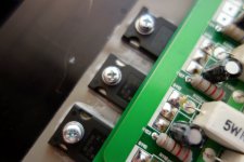
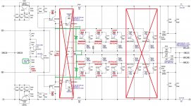
I use the spreader exactly as it is in the original design, the only difference - I use MJE340 transistors (just have got lots of them), and changed R107 to 100 ohm for shifting the bias range to higher values.
The idea to drive 3 pairs of MOSFETs directly from VAS is definitely not a good one. I would like to see full-swing 20kHz sine and full-swing rise and fall edges of the square. We might see more, then.
Pawel, I did it mostly for general "proof of concept", comparison and simulation confirmation purposes. I will though publish the full swing curves later today, but with some higher load (my 8 ohm load resistor will explode at 120V p-to-p, same as OPS itself at a relatively small test bench heatsink)...
Cheers,
Valery
Valery, waiting intently for your results with the buffer stage...
If you get the time, would you kindly sim the results with a single pair of FETs hung off the VAS at, say, 20kHz 22Vrms?
If you get the time, would you kindly sim the results with a single pair of FETs hung off the VAS at, say, 20kHz 22Vrms?
Now with EF buffer in front of MOSFETs
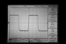
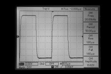
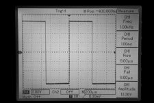
OK. The one with the follower. This one is excellent. EF works at 10mA. Drives 3 pairs of MOSFETs very well. You can see the Bode plot is somewhat flatter on the right (it actually copies the plot taken from the front-end with no OPS). Square waves are much better - no overshoot. Lower voltage ones are taken with 8 ohm load, higher voltage ones (80-100V p-to-p) - with 23 ohm (otherwise the load started burning). Again - everything looks close to simulation. THD20 is definitely lower than the one with no EF.
I have ordered Lynx L22 - planned to do it some time, but now my e-mu got broken, so - it's time for change. Looking forward to seeing the spectrums 😉
Sounds very impressive. I could not pump-up some real power (1:20AM here), however at couple of watts it's excellent. More listening - tomorrow.
See the schematic - changes are minimal. I use small aluminium heatsinks on MJE340/350 follower transistors - they are moderately warm at 10mA.
Have fun!
Cheers,
Valery
Attachments
Sounds very impressive. I could not pump-up some real power (1:20AM here), however at couple of watts it's excellent. More listening - tomorrow.
Have fun!
Cheers,
Valery
Now you're getting somewhere close hehe 😉
P.S. It takes no more than 5 x 10 cm, output inclusive. 😎
Attachments
Last edited:
Yeah, at the moment the front-end is slightly over-compensated (after some stability experiments) - it actually limits the bandwidth, etc. I'm going to try to reach the optimum for this combination (IPS - OPS) later on 😉
Valery, waiting intently for your results with the buffer stage...
If you get the time, would you kindly sim the results with a single pair of FETs hung off the VAS at, say, 20kHz 22Vrms?
Ranchu, I ran the sim with these parameters - even one pair loads the cascode (at 4.7mA) too much - THD20 grows 5 times (though at 1 KHz it's no problem)... Together with EF it's coming back to normal. So... either increase the VAS / cascode current (possible with lower rails, mine are +/-70V now) or use the follower 😉
Cheers,
Valery
Valery, can you measure bias current when mosfet cold and warm? I want to know the bias current stability.
Valery, can you measure bias current when mosfet cold and warm? I want to know the bias current stability.
Hi Bimo, just tested from the "cool" condition.
As you power on the cool one, it jumps to 200mA, then within 30 seconds lowers to 120mA, then within the next minute comes down to 60mA and stays there.
Cheers,
Valery
Hi Bimo, just tested from the "cool" condition.
As you power on the cool one, it jumps to 200mA, then within 30 seconds lowers to 120mA, then within the next minute comes down to 60mA and stays there.
Cheers,
Valery
Thank you, Valery.
I sim simple CFA (VSSA input) with mosfet output like Valery schematic.
THD at 20kHz rise significantly high from 70W/8Ohm to 180W/8Ohm.
May be it nature of mosfet or my model is wrong.
.model irfp240C VDMOS(nchan Vto=4.0 Kp=4.8 Lambda=0.0032 Rs=0.01 Rd=0.1 Rds=1e7 Cgdmax=2600p Cgdmin=10p a=0.35 Cgs=1250p Cjo=3000p m=0.75 VJ=2.5 IS=4.0E-06 N=2.4)
.model irfp9240C VDMOS(pchan Vto=-3.76 Kp=9 Lambda=0.004 Rs=0.064 Rd=0.1 Rds=1e7 Cgdmax=1200p Cgdmin=15p a=0.26 Cgs=1130p Cjo=2070p m=0.68 VJ=2.5 IS=4.0E-06 N=2.4)
Sim result:
PM 71 GM 16
180W/8Ohm, 1kHz -> 0.000787%
180W/8Ohm, 20kHz -> 0.011327%
70W/8Ohm, 1kHz -> 0.000433%
70W/8Ohm, 20kHz -> 0.003806%
SR ~120
Attachments
- Home
- Amplifiers
- Solid State
- Slewmaster - CFA vs. VFA "Rumble"