I have not read the 6th edition yet. Regarding maximum safe (stability issues) loopgain at 20kHz, do you still recommend 30dB (up to 40dB with great care)?
2-pole compensation schemes change that, even 60 dB @20k becomes possible
while Pavel likely knows, others seem to need reminding "TMC" is a 2-pole compensation and has to be measured as total feedback around the output device, "inside" the TMC loop, not just the global
while Pavel likely knows, others seem to need reminding "TMC" is a 2-pole compensation and has to be measured as total feedback around the output device, "inside" the TMC loop, not just the global
I have not read the 6th edition yet. Regarding maximum safe (stability issues) loopgain at 20kHz, do you still recommend 30dB (up to 40dB with great care)?
I am still using 29 or 30 db at 20 kHz. It always works, in my experience.
I don't think I have ever said that 40 dB at 20 kHz can be used with great care. I suspect that it would not be reliably stable. It would be interesting to see much Cdom can be reduced before things take off, though you would probably be affecting the pole-splitting as well as the o/l gain. Reducing the input pair emitter resistors might be a safer way of proceeding.
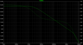
How about this loopgain plot (stable enough, in a real world).
What I have learned during this work is that the loop should not be simulated in idle for the power stage. I have found that off-setting the output to ~10V DC and then measure the loop is the best way to get a stable design.
So I cannot answer your question without knowing the measurement setup.
\\\Jens
Last edited:
How about this loopgain plot (stable enough, in a real world).
I assume that's a simulation?
2-pole compensation schemes change that, even 60 dB @20k becomes possible
while Pavel likely knows, others seem to need reminding "TMC" is a 2-pole compensation and has to be measured as total feedback around the output device, "inside" the TMC loop, not just the global
Hi,
Please excuse my ignorance, what is ”TMC” short for?
\\\Jens
2-pole compensation schemes change that, even 60 dB @20k becomes possible
It does? Please show me how.
while Pavel likely knows, others seem to need reminding "TMC" is a 2-pole compensation and has to be measured as total feedback around the output device, "inside" the TMC loop, not just the global
Since there is no peaking of the open-loop gain with "TMC", more commonly known as Output-Inclusive Compensation, I don't see how it can be called 2-pole compensation in the accepted sense.
I hope this is not the lid coming off the can.
I assume that's a simulation?
Yes it is, but I have measurements as well.
Regarding jcx and other than Cdom schemes, I agree that 30 - 40 dB is not a limit.
Hi,
Please excuse my ignorance, what is ”TMC” short for?
\\\Jens
Try to search this forum.
Something wrong with your simulation, I think.
Well, surely there's your problem. No current-limiting.
It's easy to say, the simulation is wrong, try to simulate the case by yourself.
Could you explain how to push the VAS current higher than the current set by CCS just with hard clipping, I would like to learn here.
Since there is no peaking of the open-loop gain with "TMC", more commonly known as Output-Inclusive Compensation, I don't see how it can be called 2-pole compensation in the accepted sense.
I hope this is not the lid coming off the can.
Well Mr. Self, yes, this is a can of worms. Indeed TMC (or "output inclusive" as you call it) is a 2 pole compensation method. This was discussed here in extenso, and lots of valid theoretical reasoning was provided. To me, the most conclusive proof was the mathematical equivalence of the "output inclusive" schema with a regular 2 pole compensation network, plus a lead-lag compensation network. This is relatively easy to prove using a Wye-Delta transformation of the "output inclusive" network. The physical interpretation of this equivalence is a 2 pole compensation loop gain/phase shape, and a lead lag compensation that removes the phase dip before the unity loop gain frequency, which creates the illusion that "output inclusive" compensation is "single pole".
The bottom of this is that much care has to be taken in using "output inclusive" compensation. Enough phase margin in the global feedback loop doesn't guarantee good stability, since the inner (or minor) feedback loop can be dangerously close to the stability limit.
This "2 pole" equivalence" does not, by any means, diminish the value and cleverness of this technique. It's only that it is not the holy grail that so many people believed in, bust another proof that the Bode integrals and the Maximum Feedback Theorem are limiting the amount of feedback (loop gain) available for linearizing an amplifier, disregarding how "clever" we get. Doesn't matter how much we struggle, gain and phase in an audio amplifier are not independent variables.
I know these things can be rather slippery, and may raise more questions that they answer, so before going into any details, I must ask what would you consider as valid proof that "output inclusive" is 2 pole compensation method. BTW, it took Mr. Cordell about six months to buy into this, now he fully agrees with this "2 pole" view of TMC/"output inclusive".
Could you explain how to push the VAS current higher than the current set by CCS just with hard clipping, I would like to learn here.
Saturation - then the CCS may no longer behave like a CCS.
I believe clipping behavior is one glaring difference between the symmetrical and Blameless topologies, and it's not favoring symmetrical topologies, unless extra complexity is added to avoid saturation and/or kill the loop gain when clipping occurs.
It does? Please show me how.
Since there is no peaking of the open-loop gain with "TMC", more commonly known as Output-Inclusive Compensation, I don't see how it can be called 2-pole compensation in the accepted sense.
I hope this is not the lid coming off the can.
This is a simulation, but that amp was built and is working with no problem ever sins.
It is my TT amp, presented here in one thread. The loop gain at 20 kHz is 67 dB. It is two pole compensation and it shows that with correct simulation.
Attachments

Saturation - then the CCS may no longer behave like a CCS.
I believe clipping behavior is one glaring difference between the symmetrical and Blameless topologies, and it's not favoring symmetrical topologies, unless extra complexity is added to avoid saturation and/or kill the loop gain when clipping occurs.
Yes, but then the EF transistor is already destroyed.
For push-pull EF-VAS it is exactly that protection resistors connected between EFs collectors and the ground to prevent saturation and produce nice clipping behavior. A current limiting is not allowed as it prevents a current on demand needed for high SR.
as Waly suggested, Cordell seemed convinced in the end with our/my analysis, supported by a few others that use EE feedback theory at a competent level
"TMC" (Transitional Miller Compensation, name seems to be used locally - what other coinages?) does apply 2nd order loop gain around the output device, has the same stability cost as doing it in the global loop
some distracting arguments were going back and forth about exact equivalence of part values, differing C ratios, trimming peaking with outer lead C...
but I believe it is fair to say that most of us arguing at that level of detail accepted that "TMC" is essentially a variation of 2-pole compensation
different people find different arguments more persuasive - I did the equations for myself in MathCad, but even I have to fight eyes glazing over when I go back to them - I thought simulations would be more accessible to many here
In particular I thought my added delay sim was a pretty dramatic demonstration of TMC stability not being the same as a Miller comp with a similar looking "single pole" outer loop gain
http://www.diyaudio.com/forums/soli...lls-power-amplifier-book-134.html#post2420438
using Blackman's relations you can also see the region of 2nd order loop gain effect external to the loop
http://www.diyaudio.com/forums/soli...lls-power-amplifier-book-110.html#post2406839
and of course simplest of all is just take the suggestion to put the loop gain probe inside all loops, cutting between the output Q and both the inner loop "bootstrap" R and global feedback parts
Last edited:
For push-pull EF-VAS it is exactly that protection resistors connected between EFs collectors and the ground to prevent saturation and produce nice clipping behavior. A current limiting is not allowed as it prevents a current on demand needed for high SR.
An EF never saturates, Vce cannot go under Vbe. If you add a collector resistor, then that's no longer an "EF" and it can saturate. But then the "EF" collector resistor limits the current.
An EF never saturates, Vce cannot go under Vbe. If you add a collector resistor, then that's no longer an "EF" and it can saturate. But then the "EF" collector resistor limits the current.
Waly, not disagreeing with your reasoning, but Vce can go below Vbe. I've seen Vce's down to a few 100 mV.
Jan
An EF never saturates, Vce cannot go under Vbe. If you add a collector resistor, then that's no longer an "EF" and it can saturate. But then the "EF" collector resistor limits the current.
Yes, my bad, but VAS can saturate, if the EF does not burn before.
Last edited:
Waly, not disagreeing with your reasoning, but Vce can go below Vbe. I've seen Vce's down to a few 100 mV.
That's not saturation, saturation is at Vce=0. If you tie the base to the collector in an EF, then Ic=(Vcc-Vbe)/Re and Vce=Vcc-Ic*Re= Vbe. Of course, if Vcc>>Vbe, then Ic->Vcc/Re and Vce->0, but is never zero, hence the EF never saturates.
- Status
- Not open for further replies.
- Home
- Amplifiers
- Solid State
- Your opinions are sought on Audio Power Amplifier Design: 6th Edition. Douglas Self