I have always wanted to find and walk my own path, so to speak 😉.
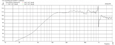
Output in this condition was 110dB @ 50Hz, at 50cm away from mouth (almost 1pi conditions, rear wall is close) with ~2,78V. It might get somewhat better after complete sealing. SPL-meter is the Radioshack digi, but it shouldn't make noticeable error in this frequency. 🙂
Output in this condition was 110dB @ 50Hz, at 50cm away from mouth (almost 1pi conditions, rear wall is close) with ~2,78V. It might get somewhat better after complete sealing. SPL-meter is the Radioshack digi, but it shouldn't make noticeable error in this frequency. 🙂
The low pass effect of the rear wave is very real, but the front tap of the cones radiate quite unhindered into the listening space.
Like most subs, you will be running these with a low pass filter set at say 100 Hz, right? So the mids and highs that may leak out of any tapped-driver design is a non-issue.
110dB at 0.5m 2.78V in 1pi is about 103dB at 1m, 2pi. Which is still pretty good. You may get 104dB to 105dB once you are up to 2.83V. That is pretty sensitive for a sub in any book.
Yes, around 100Hz, seems like 2nd order filter might doable.
Besides possible leaking (top plate is only laying on the frame), also room modes might have affected the output. I would like to measure one of them outside once completely finished + with front horns.
By the way, regardiung measuring any horn system or a tapped on in specific, is the distance of the spl-meter calculated from the mouth, or from the voice coil of the radiator? I calculated from mouth.
Legis,
I just saw this thread by Weltersys that shows the positive effect of add-on waveguide/horns for the mouth of a sub. It looks like an easy +3dB gain (maybe more if matched to the expansion of the mouth).
http://www.diyaudio.com/forums/subwoofers/184986-horn-extender-wave-guide-th.html
How is the build coming along? Looking forward to seeing the "synergy" V-horn placed on top of the PP tapped pipe.
Legis,
I just saw this thread by Weltersys that shows the positive effect of add-on waveguide/horns for the mouth of a sub. It looks like an easy +3dB gain (maybe more if matched to the expansion of the mouth).
http://www.diyaudio.com/forums/subwoofers/184986-horn-extender-wave-guide-th.html
How is the build coming along? Looking forward to seeing the "synergy" V-horn placed on top of the PP tapped pipe.
Thanks for the link, X! According to simulations, +4-6dB is gained if big enough horn extender is used. It also smoothens (maybe) the response because I fine tuned the tapped sections keeping the front horn in mind.
The build is coming along nicely. Yesterday made the throat pieces for the synergy horns and the pieces that attach the comps to the throat. I have also made the ~30 litre back chambers of the Deltalites. Another tapped horn's frame is ready and drying, I'm going to put in the wavequides next. Deltalites should be here tomorrow or the day after.🙂
An externally hosted image should be here but it was not working when we last tested it.
An externally hosted image should be here but it was not working when we last tested it.
An externally hosted image should be here but it was not working when we last tested it.
An externally hosted image should be here but it was not working when we last tested it.
The build is coming along nicely. Yesterday made the throat pieces for the synergy horns and the pieces that attach the comps to the throat. I have also made the ~30 litre back chambers of the Deltalites. Another tapped horn's frame is ready and drying, I'm going to put in the wavequides next. Deltalites should be here tomorrow or the day after.
That is coming along very fast - cool! Can't wait to see it and hear your impressions. This is one of the coolest builds on this forum. 😎
Legis,
The horn you describe above sims pretty well. I also played with the port injection locations (assuming 12.5 cm dia port and 4 liter driver front chamber). I have it at 17.2 cm, 15cm, and 13 cm and it seems to flatten response to 500 Hz. The 30 liter rear chambers have to be heavily stuffed (aperiodic) to achieve a Q=0.05 to damp out back reflections. No low pass or high pass filters were used.
Here is the prediction for the 17.2 cm port injection location:

Here is the 15 cm port injection location:
Here is the 13 cm port injection location:
I think I'm going circular port route. They are easy to align, easy to cut, et cetera... Leaves less room for error. The furthest part of the circular port will be at 17,2 cm away from the throat.
I can fit approx 11-12cm diameter port, which gives a compression ratio of around 10:1. That is pretty huge for 15" lightweight cone, no?
The front chamber volume will be that of Delatalite 2515 + 35,7cm x 1,5cm throat piece (= 1,5 litres) + size of the throat port (around 0,15 - 0,2 lires). Deltalite's cone might even have around 3-4 litres of volume?
Last edited:
If you want, use dry beans poured into the cones to estimate volume (or use geometry) and I can plug it into the model and use your actual injection port location and dia to run another sim. The model currently uses 4 liters for the driver chamber volume. The volume of the port itself is automatically accounted for by specifying dia and length.
Your CD adapter mount looks really nice. Your woodwork looks great in general. How much plywood is this project using? Substantial amount I would guess.
Your CD adapter mount looks really nice. Your woodwork looks great in general. How much plywood is this project using? Substantial amount I would guess.
You are way over on the actual cone volume. I can't recall the exact volume I measured with puffed rice. I think it was either 1.25l or 2.25l...
Thanks NEO Dan for the info. If those two are the options, I think they are 2,25l.
I don't have the drivers yet but I will measure them when they get here. In the meantime you can use 2,25 litres.
The routed the injection ports and throat pieces for the Deltalites, heres a pic Traces are bit blurry because the lighting was bad.
- The port starts at the edge of the cone, or cone's surround actually.
- The furthest edge of the port is ~17,2cm away from the throat. Port's diameter is 11cm so the closest edge of the port is ~6,2cm away from the throat.
- Port's center is approx. 123,5 millimetres offset (closer to the throat) than the driver's center.
Thanks for the kind words. I think the amount of plywood is around 22-23m2, give or take (without the front horns!). That is for 2pcs synergies + 2pcs tappeds.🙂
If you want, use dry beans poured into the cones to estimate volume (or use geometry) and I can plug it into the model and use your actual injection port location and dia to run another sim. The model currently uses 4 liters for the driver chamber volume. The volume of the port itself is automatically accounted for by specifying dia and length.
Your CD adapter mount looks really nice. Your woodwork looks great in general. How much plywood is this project using? Substantial amount I would guess.
I don't have the drivers yet but I will measure them when they get here. In the meantime you can use 2,25 litres.
The routed the injection ports and throat pieces for the Deltalites, heres a pic Traces are bit blurry because the lighting was bad.
- The port starts at the edge of the cone, or cone's surround actually.
- The furthest edge of the port is ~17,2cm away from the throat. Port's diameter is 11cm so the closest edge of the port is ~6,2cm away from the throat.
- Port's center is approx. 123,5 millimetres offset (closer to the throat) than the driver's center.
An externally hosted image should be here but it was not working when we last tested it.
Thanks for the kind words. I think the amount of plywood is around 22-23m2, give or take (without the front horns!). That is for 2pcs synergies + 2pcs tappeds.🙂
I can get dimensions for you, I still have a fresh driver in storage.
The more I think about the volume I am not so confident, it's been a few years at this point. 😱 I don't see any Hornresp records with front volume for this driver so I am probably mistaken about which 15" I measured. I may pick up a bag of rice cereal and measure again...
The more I think about the volume I am not so confident, it's been a few years at this point. 😱 I don't see any Hornresp records with front volume for this driver so I am probably mistaken about which 15" I measured. I may pick up a bag of rice cereal and measure again...
Legis V-horn Synergy with Deltalites
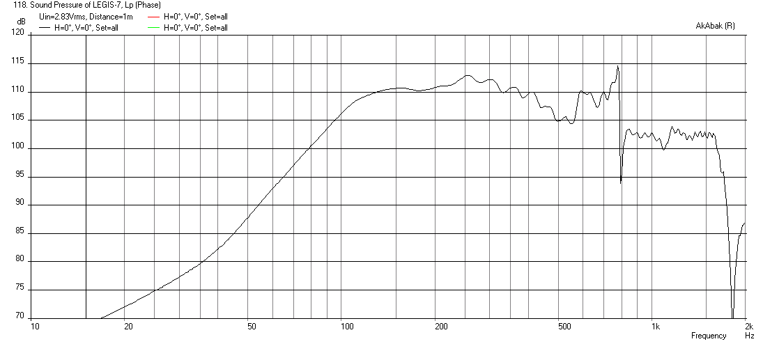
Here is the sim with 12 cm dia injection ports located at 11.2 cm from throat and 2.25 liter volume compression chambers. 30 liter back chambers. Looks pretty good - a nice wide bandwidth from 100 Hz to 1kHz - you could use a 1 in CD if you had to and cross at 1kHz.
12 cm dia injection port at 11.2 cm from throat:

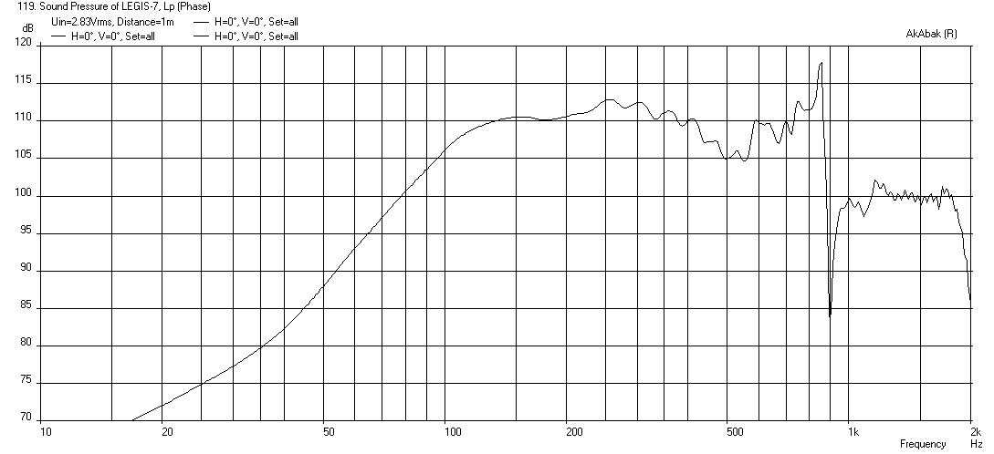
11 cm dia injection port at 11.7 cm from throat:
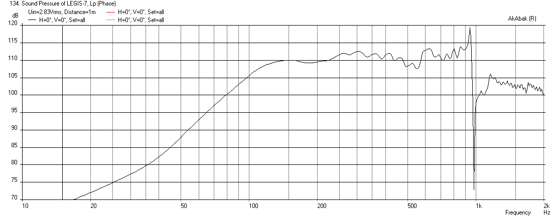
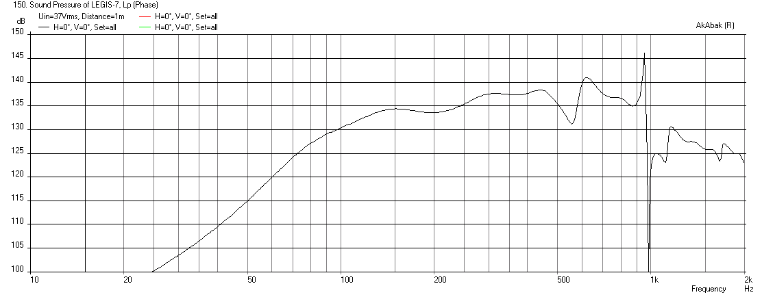
Here is 11 cm dia port at 11.7 cm from throat driven to xmax of 4.8mm:
Here is the sim with 12 cm dia injection ports located at 11.2 cm from throat and 2.25 liter volume compression chambers. 30 liter back chambers. Looks pretty good - a nice wide bandwidth from 100 Hz to 1kHz - you could use a 1 in CD if you had to and cross at 1kHz.
12 cm dia injection port at 11.2 cm from throat:
11 cm dia injection port at 11.7 cm from throat:
Here is 11 cm dia port at 11.7 cm from throat driven to xmax of 4.8mm:
Attachments


Last edited:
That sim looks great. Is the open back still looking like a decent option?
The large round hole consuming the entire horn wall might mess with the performance; Danley tends to shove the entry points into the corners:
The large round hole consuming the entire horn wall might mess with the performance; Danley tends to shove the entry points into the corners:
An externally hosted image should be here but it was not working when we last tested it.
Neodan,
I had the same concern about a 12cm hole on the wall of the horn as not being the best thing for the HF CD. This is something that can be modified by plugging up the big round hole and putting several snaller slots along the corners. If may just turn out ok - we will know soon enough once Legis finishes the build and takes a measurement.
I had the same concern about a 12cm hole on the wall of the horn as not being the best thing for the HF CD. This is something that can be modified by plugging up the big round hole and putting several snaller slots along the corners. If may just turn out ok - we will know soon enough once Legis finishes the build and takes a measurement.
That sim looks excellent. However the volume of the throat chamber should have been increased by 1,5 litres in the sim because of the throat adapter that the Deltalites will have (Deltalite's cone 2,25l + throat chamber 1,5l). I made the adater from of 1,5cm thich plywood so they cannot ever destroy their cones by over excursion and hitting the opposite wall.
The port will be 2,7cm deep.
This might limit the bandwidth to some extent. Some extra acoutical low pass might be even prefered since I don't need the bandwidth to be that high (lowers distortion).
Basically one could also add slight damping material to the front chamber to increase acoutical low pass, but would it decrease sensitivity?
I hope those ports do not screw too much with the comps' response. Space was quite limited to route decent sized ports for big drivers. Smaller drivers would have been easier since they need smaller ports. However smaller ones do not sound quite the same as bigger elephant ears.😀
You could probably get by with a pass of the router for cone clearance as you did for the compression driver mounting bolts. I would avoid pushing the cone excursion very far as the cone is very lightly made. The driver appears to be more of a low mid than mid bass. The sensitivity this design offers is really key to the performance of this driver. Loads of zip but not much horse power, push it real hard and it will sound like a Tina Turner cover band.
You could probably get by with a pass of the router for cone clearance as you did for the compression driver mounting bolts. I would avoid pushing the cone excursion very far as the cone is very lightly made. The driver appears to be more of a low mid than mid bass. The sensitivity this design offers is really key to the performance of this driver. Loads of zip but not much horse power, push it real hard and it will sound like a Tina Turner cover band.
Yes that was the original plan but I don't mind the extra 1,5 litres of the dedicated adaptor plate. It leaves me also an option to put in absorbing and/or bitumen sheet in the front chamber if mechanical resonances need taming or I want to strenghten the acoutical bandpass.
Here's quick sketch of the construction: The adaptor plate will have all the insert threads for the screws of the drivers and back chamber. I will glue the plates together with expanding polyurethane wood glue (like everytning else), so possible gaps are filled inside.
An externally hosted image should be here but it was not working when we last tested it.
Legis,
Your idea of a big mounting plate adapter gives you lots of flexibility in injection port holes. I guess you are committed to holes located where they are. Let me sim multiple slot ports located farther away and see how that works. I am exploring because I feel you may get a lot of coloration and loss of efficiency with the CD having such big holes near the critical early throat expansion. You may be able to move location of injection anothe 8 inches to 10 inches away. Don't know if that will affect bass extension too much?
Your idea of a big mounting plate adapter gives you lots of flexibility in injection port holes. I guess you are committed to holes located where they are. Let me sim multiple slot ports located farther away and see how that works. I am exploring because I feel you may get a lot of coloration and loss of efficiency with the CD having such big holes near the critical early throat expansion. You may be able to move location of injection anothe 8 inches to 10 inches away. Don't know if that will affect bass extension too much?
Legis,
Your idea of a big mounting plate adapter gives you lots of flexibility in injection port holes. I guess you are committed to holes located where they are. Let me sim multiple slot ports located farther away and see how that works. I am exploring because I feel you may get a lot of coloration and loss of efficiency with the CD having such big holes near the critical early throat expansion. You may be able to move location of injection anothe 8 inches to 10 inches away. Don't know if that will affect bass extension too much?
Thanks X, please sim the current situation with 2,25l + 1,5l front chamber total volume and anything else you like to try out regarding the injection port's location.
Moving ports further away from the throat will also lower the null frequency. I used 17,2cm because it is (I think it is) "by the book" for 500-600Hz crossover frequency.
It's interesting to see how the ports affect the comp's output. I can always modify the ports, it's quite easy to fill old/route new. Best would be if this arrangement works fine, I like the looks of big ports. One big port also cannot introduce comb filter effect (however that might be shown in horn's output) like two separated ports can if the xo frequency is too high compared to the greatest distance between the ports.
Maybe the effect of the port could be mitigated to some extent by adding some absorbing felt around the perimeter of the port? The goal would be to make the ports "invisible" to waves inside the horn, and at the same time make them "visible" to the waves that come from Deltalites. Like a one sided mirror, or "acoutical diode" that only allows passage to one direction and blocks the other way.
Maybe covering the whole ports with a cloth, that is slightly painted (so it reflects higher frequencies) on the horn's side could work to some extent???
Last edited:
- Status
- Not open for further replies.
- Home
- Loudspeakers
- Subwoofers
- Study of a Dipole/Cardioid Bass Horn