I built an exponential TH that works like this so that when you have a stack of 8 the FR is flat to the cut off. It's a beast.


NeoDan,
Is that a real stack-o-8 or a rendering? That wall of power would indeed be something to behold. 😀
Can you show the fold geometry, I am having a hard time seeing how you wrapped it up and how big it is.
Is that a real stack-o-8 or a rendering? That wall of power would indeed be something to behold. 😀
Can you show the fold geometry, I am having a hard time seeing how you wrapped it up and how big it is.
That's a real.... rendering, that's what it is 😉
Here's another one in HD to drool on 😀

Ancient Chinese secret: a creative guy with scissors could reconstruct the fold from the expansion image...
Here's another one in HD to drool on 😀
Ancient Chinese secret: a creative guy with scissors could reconstruct the fold from the expansion image...
I built an exponential TH that works like this so that when you have a stack of 8 the FR is flat to the cut off. It's a beast.
Really nice behaviour based on the sim! Do you have some measured data?
Legis,
I actually built dozens of nested horn cabinets back in 1992 called the Maltese horn. The Maltese used a conical expansion HF horn inside the mid, mid inside the low, and though they did approximate a point source, the Synergy design simply works far better for all the reasons you mentioned and many more.
Your speculation that the the midwoofers would not modulate the compression driver's diaphragm as much as they would if attached in the same horn is unfounded, modulation is not a problem in either design.
A Synergy design is also three times easier to build than a 3 way nested horn.
Art
Good to know that modulation is not usually a problem.
I have never seen THD measurements of Synergy horns at ~110dB. Something might show up if there is modulation. Compared to drivers being measured separately in the same horn.
Last edited:
I have decided to build the PPSL tapped pipes. I think their SQ can be quite good, but they do not have the last authority below 30Hz (but propably quite enough still).
So many options to fine tune the response in the end. I will use detachbale front horns, not sure yet how they should be implemented though. Perhaps I will try out them first with light weight/cheap polystyren sheets, I quess they can be used mediocrely to direct bass frequencies... Just put the front horn "on" while listening, lift it up and put away behing the speakers while not listening, convenient?😀
Here's HR sim in 1pi with 100cm long front horn placed in front of the thing. Quite low particle velocity at 1000W/19mm so only little chuffing/compression can be expected. The average efficiency between 40 and 100Hz is quite nice. These could be driven propably with 10W tube amp/t-amp.
An externally hosted image should be here but it was not working when we last tested it.
An externally hosted image should be here but it was not working when we last tested it.
An externally hosted image should be here but it was not working when we last tested it.
An externally hosted image should be here but it was not working when we last tested it.
Slight changes to the original plan. Just tilt the last two walls somewhat open, and voila, better HF extension. It seemes to cancel the deep null after 100hz (and attenuate somewhat the resonance at 170Hz that was present in previous sims).
Also the possible chamber resonance is attenuated with this arrangement because the last wall is not in parallel with the exit.
I made the front horn opening VERY big in the simulation. It's propably little overstated even if 200cm x 60cm opening is used and the floor/wall extensions are taken into account? Or does the HR predict this, floor/wall boundaries effectively increasing (doubling/tripling) the mouth area of the horn?
By the way, that is 2pi simulation. 🙂
Also the possible chamber resonance is attenuated with this arrangement because the last wall is not in parallel with the exit.
An externally hosted image should be here but it was not working when we last tested it.
I made the front horn opening VERY big in the simulation. It's propably little overstated even if 200cm x 60cm opening is used and the floor/wall extensions are taken into account? Or does the HR predict this, floor/wall boundaries effectively increasing (doubling/tripling) the mouth area of the horn?
An externally hosted image should be here but it was not working when we last tested it.
An externally hosted image should be here but it was not working when we last tested it.
By the way, that is 2pi simulation. 🙂
Last edited:
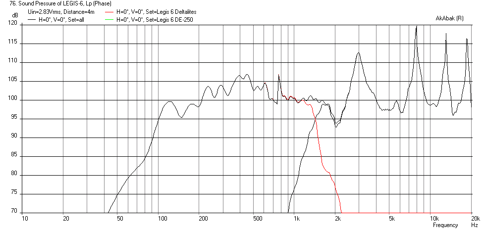
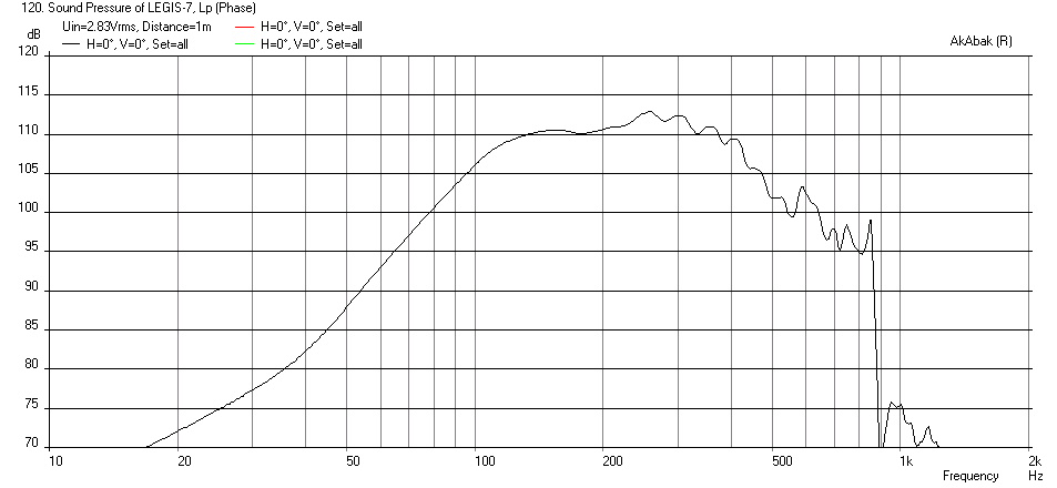
Here is what you get if you add a B&C DE-250 CD feeding a very short 2.5cm long transition duct from the CD throat to a 2.5cm wide x 50 cm tall back vertex. I also added a compression chamber between the Deltalites with an injection port leading from the chamber (formed between driver cone and horn walls) at the same location as before (17.3 cm axial distance). I estimated the chamber volume as 4 liters with a 10 cm dia injection port (or equiv area slot) going through 18mm plywood as the port length. This compression chamber and port increased the mid horn bandwidth into well above 1kHz (vs 500 Hz previously without). This is needed to properly XO with the DE-250 which has a recommended XO point at 1600 Hz. I set the XO freq at 1600 Hz, added 4 ohms of padding to the CD and gave it a 6.8uF high pass shelf to boost upper end response (this can all be done in DSP if run actively).
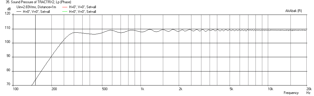
It is not a bad start given that I threw this together by adding the CD and makeshift transition duct. The CD will appear to have horn "honking" and this can only be solved by having a real horn profile or centerbody phase plug vs. a simple V geometry. A tractrix perhaps? (this may be useful as a point to start a design: http://www.volvotreter.de/downloads/Tractrix_v1.4b.zip )
Here is the Freq Response with 2.83v input at 4 meters away to give space for the mids and highs to integrate (that is some wicked sensitivity there):
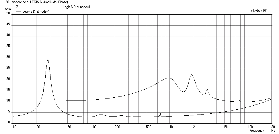
Here is the Impedance:
Here is the code if you want to play with it:
Code:| Model of Legis open back dual driver 1 m x 1m x 50 cm high V-horn with | Dual Deltalite 15's driving a compression chamber with injection ports | in a Synergy style layout with a CD feeding vertex for high frequencies | by xrk971 | July 22, 2014 | File LEGIS-6 System 'Legis 6 Deltalites' Def_Const { | ### input parameters ### | ### Define exterior physical size of speaker Width = 1.00 ; | width at mouth in meters Height = 0.50 ; | height of speaker in meters Depth = 1.00 ; | depth of speaker from cusp to mouth in meters Speaker_pos=0.25; | Speaker height above floor in meters Dist_wall=2.0; | Speaker distance from back wall in meters XO_freq=1600 ; | XO Freq between Mid and High in Hz L_tx=2.5*0.01; | Transition duct between CD throat and main V horn vertex in cm | Horn geometery S0=0.0125 ; |width of vertex in meters (small value) S1=0.173 ; |width at driver center assuming 200 mm center to edge distance for driver in meters L01=0.173 ; |distance from vertex to driver on centerline cos(30deg)*200mm=173mm S2=1.00 ; |width at mouth in meters L12=0.827 ; |distance from driver at centerline to mouth in meters | *** driver comp chamber *** Vol_driver_chmber=4.0*0.001; | vol between driver cone and inj port in liters Dia_inj=5.0 * 0.0254; | Inj port dia inches or equivalent area Q_ch=0.707; | Q of driver inj chamber (adjust with stuffin/padding between driver and port) | ## DE250 Compression Driver params ## Ree=6.3; |Voice coil resistance [ohm] ......(Re) Le=0.11e-3; |Voice coil inductance [H] ......(Le) Bl=9.3; |Motor conversion factor F=Bl*i [Tm]......(BL) Mms=1.4e-3; |Mechanical mass [kg] ......(Mms) Rms=.5; |Mechanical resistance [Ns/m] ......(Rms) Cms=30e-6; |Mechanical compliance [m/N] ......(Cms) dDi=40e-3; |Diameter centre diaphragm [m] ......(Diam of inner magnet) dDa=47e-3; |Diameter outer diaphragm [m] ......(Diam of outer chamber) Hi=1.0e-3; |Eff. height of outer chamber under the ring ......(gap between diaphragm and phase plug) Ha=4.5e-3; |Eff height of outer chamber under the ring ......(Averaged height of annular chamber) ds=0.20e-3; |Slit between voice coil and magnet ........(Annular gap between magnet and voice coil former) ls=11e-3; |Length of voice coil path .......(Length of annular gap) } Def_Driver 'Deltalite15' | Eminence Model Delatalite II 15 4.8 mm xmax, 99.2dB, Qts 0.38 SD=856.3cm2 |Piston fs=42Hz Mms=72g Qms=4.56 Qes=0.41 Re=5.29ohm Le=1.15mH Bl=15.7Tm Vas=204L | Speaker with horn axis CL at Speaker_pos above floor and Dist_wall away from back wall Def_Reflector HorizEdge Bottom={Speaker_pos} Top={Dist_wall+Depth} AbsorbCoeff=0.3 HAngle=0 VAngle=0 Filter 'HighPass' |Highpass filter -12dB/oct BW fo=95Hz vo=1 {b2=1; a2=1; a1=1.414214; a0=1; } | *** Cross-over (XO) frequency from Mids to Highs *** Filter 'Low Pass' | 4th order Butterworth Low Pass -24dB/oct set crossover freq at 2500 Hz fo={XO_freq} vo=1.0 {b0=1; a4=1; a3=2.613126; a2=3.414214; a1=2.613126; a0=1; } | Define driver to be used and wired in parallel (left driver when viewed from front Driver Def='Deltalite15' 'Driver 1' Node=1=0=111=201 | Right driver when viewed from front Driver Def='Deltalite15' 'Driver 2' Node=1=0=112=202 | *** option to put chambers with ducts leading to horn injection point *** Enclosure 'Driver Chamber 1' Node=111 Vb={Vol_driver_chmber} Qb/fo={Q_ch} Lb=1in | keep chamber very flat - circa 1 in from cone to port | *** duct from driver 1 compression chamber to horn injection point *** Duct 'Inject Port 1' Node=111=11 dD={Dia_inj} Len=0.719in | Thickness of wall plywood Enclosure 'Driver Chamber 2' Node=112 Vb={Vol_driver_chmber} Qb/fo={Q_ch} Lb=1in | *** duct from driver 2 compression chamber to horn injection point *** Duct 'Inject Port 1' Node=112=11 dD={Dia_inj} Len=0.719in | Thickness of wall plywood | Backside of drivers are radiators angled at 30 deg back - left driver angled left back Radiator 'Rear_Rad1' Def='Driver 1' Node=201 x=-0.173m y=0 z=-0.827m HAngle=-30 VAngle=0 WEdge={Width/2} Hedge={Height/2} Reflection Label=10 | Right driver back radiator angled back right Radiator 'Rear_Rad2' Def='Driver 2' Node=202 x=0.173m y=0 z=-0.827m HAngle=30 VAngle=0 WEdge={Width/2} Hedge={Height/2} Reflection Label=20 | ### HORN WAVEGUIDE Waveguide 'Horn Seg 1' | From vertex to driver at node=11 (both drivers excite node 11 Node=10=11 STh={S0*Height} SMo={S1*Height} Conical Len={L01} Waveguide 'Horn Seg 2' | From driver injection point to mouth Node=11=12 STh={S1*Height} SMo={S2*Height} Conical Len={L12} | ### Main horn mouth radiator Radiator 'Horn Mouth' Def='Horn Seg 2' Node=12 x=0 y=0 z=0 HAngle=0 VAngle=0 WEdge={Width/2} Hedge={Height/2} Reflection Label=20 | **** | **** New system for CD Portion with same waveguide *** | **** System 'Legis 6 DE-250' | *** XO from low freq to high high pass *** Filter 'High Pass' | 4th order Butterworth -24dB/oct set XO freq at 1500 Hz fo={XO_freq} vo=1.0 {b4=1; a4=1; a3=2.613126; a2=3.414214; a1=2.613126; a0=1; } | *** padding resisitor and boosting HP shelf cap (can all be done in DSP EQ if desired) *** Resistor 'CDPad' Node=1=350 R=4ohm | Padding resistor to attenuate CD relative to woofer Capacitor 'CDHP' Node=1=350 C=6.8uF | High pass shelf capacitor | Model of B&C DE250 Compression driver |Voice coil (frequency-non-linear resistance and reactance) Impedance 'Ze' Node=350=502 Z={ Ree*(1 + f/25e3) + j*(w*Le)^0.5; } |.......(f/? , w*Le^?) |Motor Gyrator 'Gy1' Node=502=0=503=504 Bl={Bl} |Reverse side with enclosure Coupler Node=504=0=100 dD={dDa} Enclosure 'Eb' Node=100 Vb=5cm3 Qb/fo=0.0008 | .......(Vb , Qb/fo) |Mechanical part (Mms frequency depending, cut-off at ? kHz) Impedance 'Zms' Node=503=505 Z={ wo=2*pi*15000; Zms=Rms + j*(w*Mms/(1 + w/wo) - 1/(w*Cms)) } | ......(2*pi*?) |Outer diaphragm (ring) with cavity Coupler Node=505=506=200 SD={ pi*(sqr(dDa/2)-sqr(dDi/2)) } Enclosure 'Efo' Node=200 Vb={ Ha*pi*(sqr(dDa/2)-sqr(dDi/2))} |Centre diaphragm with compression chamber Coupler Node=506=0=300 dD={dDi} Enclosure 'Efi' Node=300 Vb={ SD=pi*sqr(dDi/2); Vb=SD*Hi } |Voice coil tunnel between outer ring cavity and compression chamber Duct 'Dvp' Node=200=300 SD={ U=pi*dDi; SD=U*ds } Len={ ls } QD/fo=0.003 | .......(QD/fo) |Horn inside compression driver Waveguide 'Wpp' Node=300=10 dTh=2.32cm dMo=1in Len=3.0cm Conical |......dTh, dMo, Len | Couple CD throat exit to node=10 of main waveguide internal horn inside Beta 10CX | *** Transition duct from CD to main V horn *** Waveguide 'Horn Seg 0' | From CD throat to imternal horn mouth node=10=11 Node=10=11 STh=4.46cm2 | area is exit of CD SMo={S0*Height} | Set same as vertex area Len={L_tx} | Set length of transition from CD throat to V horn vertex Conical | *** Same V horn as above system for Deltalites *** Waveguide 'Horn Seg 1' | From vertex to driver at node=11 (both drivers excite node 11 Node=10=11 STh={S0*Height} SMo={S1*Height} Len={L01} Conical Waveguide 'Horn Seg 2' | From driver injection point to mouth Node=11=12 STh={S1*Height} SMo={S2*Height} Len={L12} Conical | ### Main horn mouth radiator Radiator 'Horn Mouth' Def='Horn Seg 2' Node=12 x=0 y=0 z=0 HAngle=0 VAngle=0 WEdge={Width/2} Hedge={Height/2} Reflection Label=30
I will still at least try out "Synergizing" these, when they are ready: 🙂
An externally hosted image should be here but it was not working when we last tested it.
The mouth will be approx 80cmcm x 100cm. The throat will be approx. 7cm x 10cm which I will make with smooth transition to 2" comp. So no more a tall vertex/rapid expansion at the throat. Lenght might be around 93cm in the end. The Deltalite 2515's will have back chambers of around 30 litres of inner volume.
How would this kind horn simulate with some HF comp at Akabak?
Last edited:
Since the back horn wall is now smaller, am I to assume Deltalites will be coupled into horn using injection ports rather than full face at same location as previous sim? This increases the upper bandwidth of the horns anyway so you can cross higher than 500 Hz if desired.
Since the back horn wall is now smaller, am I to assume Deltalites will be coupled into horn using injection ports rather than full face at same location as previous sim? This increases the upper bandwidth of the horns anyway so you can cross higher than 500 Hz if desired.
Yes, I will route ports/slots for the Deltalites through the sides, propably try to stay closer than 17,2cm from the throat so the first null appears much higher than the intended xo point at 500-600Hz.
The mouth will be approx 80cmcm x 100cm. The throat will be approx. 7cm x 10cm which I will make with smooth transition to 2" comp. So no more a tall vertex/rapid expansion at the throat. Lenght might be around 93cm in the end. The Deltalite 2515's will have back chambers of around 30 litres of inner volume.
How would this kind horn simulate with some HF comp at Akabak?
Legis,
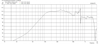
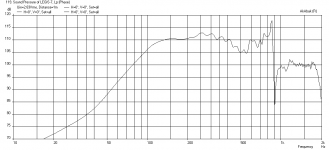
The horn you describe above sims pretty well. I also played with the port injection locations (assuming 12.5 cm dia port and 4 liter driver front chamber). I have it at 17.2 cm, 15cm, and 13 cm and it seems to flatten response to 500 Hz. The 30 liter rear chambers have to be heavily stuffed (aperiodic) to achieve a Q=0.05 to damp out back reflections. No low pass or high pass filters were used.
Here is the prediction for the 17.2 cm port injection location:
Here is the 15 cm port injection location:
Here is the 13 cm port injection location:
Attachments
Thanks for the sims! I don't quite like those resonances the ports introduce. Does non-circular port reduce thoise resonances? I planned to use "keystone" shaped ports or something quite similar:
I made a quick hack and placed the JBL 2446J behind the horn without any mouth pieces nor transition smoothing, horn placed un-optimally on the floor etc.
Here's the result at ~1,8m distance. I was surprised how well they measured and sounded.
(the last octave resonances are natural for the original JBL's ribbed diaphragm of 2446J, not related to horn itself)
I made a quick hack and placed the JBL 2446J behind the horn without any mouth pieces nor transition smoothing, horn placed un-optimally on the floor etc.
An externally hosted image should be here but it was not working when we last tested it.
Here's the result at ~1,8m distance. I was surprised how well they measured and sounded.
(the last octave resonances are natural for the original JBL's ribbed diaphragm of 2446J, not related to horn itself)
An externally hosted image should be here but it was not working when we last tested it.
Last edited:
Legis,
The resonances are above the 500 Hz XO you intend to use. If you you apply a -24dB/oct LPF at 500Hz you get this, which I think is very usable:
Or are you concerned about those little 1dB ripples from 250 hz to 500 Hz?
Your CD and horn combo measures very well - looks like it should integrate very well when used with a 500 Hz XO for the other drivers. The overall high sensitivity of the system is probably in the 110dB range is fantastic. Could probably use a 2 watt amp 🙂
Regarding keystone port holes, they may help but Akabak is 1-d model and cannot get that fine detail. V-slit with same CSA as the round port may be useful too. Also, a frustrum (cut away back side wood until a sharp edge remains on the interior wall of horn) has also been shown to help.
Good luck! It looks like it really is taking shape. This will be an incredible system when done.
Attachments
Last edited:
Legis,
The resonances are above the 500 Hz XO you intend to use. If you you apply a -24dB/oct LPF at 500Hz you get this, which I think is very usable:
Or are you concerned about those little 1dB ripples from 250 hz to 500 Hz?
Your CD and horn combo measures very well - looks like it should integrate very well when used with a 500 Hz XO for the other drivers. The overall high sensitivity of the system is probably in the 110dB range is fantastic. Could probably use a 2 watt amp 🙂
Regarding keystone port holes, they may help but Akabak is 1-d model and cannot get that fine detail. V-slit with same CSA as the round port may be useful too. Also, a frustrum (cut away back side wood until a sharp edge remains on the interior wall of horn) has also been shown to help.
Good luck! It looks like it really is taking shape. This will be an incredible system when done.
Those ripples do not scare me, although I would like to use 1-2 order filter there where possible for the best coherency.
I will at least round the edges of the ports, not sure if I want to make 15mm walls any thinner. The pressure inside the throat chamber might resonate thinner walls more, based on a layman's logic.
Yes the sensitivity of the system will be quite amazing. The least sentive drivers will be my Visaton TL16H horn super tweeters, coming in at a mere 101-102dfB/2,83V after removal of the ferro fluid (increased sensitivty by couple of dB's). I will also try to get their sensitivity up with some 1cm x 1cm x 3cm neo magnets attached on the backside of the ferrite motor. Never actually tried that but I think it will increase the magnetic flux.
Legis,
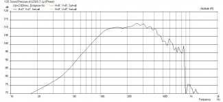
You may be interested in this thread (http://www.diyaudio.com/forums/full-range/259293-prv-5mr450-ndy-fast-applications.html) if you are looking for a 300 Hz to 15kHz driver/horn combo. The new PRV 5MR450-NDY coupled to a tractrix horn has nearly 110 dB sensitivity at 2.83v and 1m.
Here is the predicted response:
I measured the response in an OB and got something very similar to factory data so I trust their measurement more.
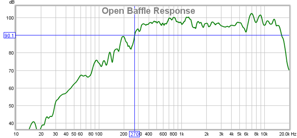
Last edited:
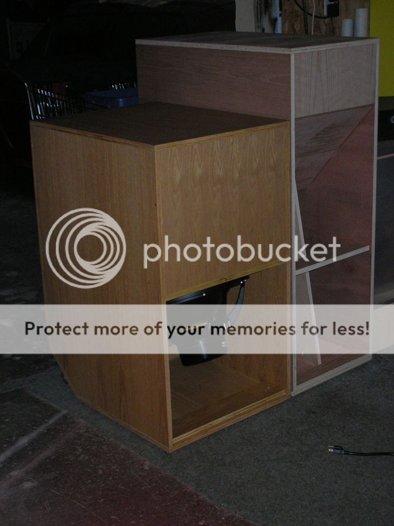
First tapped horn is ready to be listened in test purposes to satisfy the curiosity. Pardon the mess!😉
I'm just running it full range. It seems to have high sensitivity. It's very easy to exceed 100dB peaks with this thing when listening, while not really realizing one's listening that loud. The top plate was only placed upon the thing with some added mass, it leaks and resonates when listening moderately loud. Sounds better at lower volumes but one cannot make any judgements in the current state. Sounds promising nevertheless. I did not put on the "wave directors" yet either in the angles/corners.
An externally hosted image should be here but it was not working when we last tested it.
An externally hosted image should be here but it was not working when we last tested it.
I'm just running it full range. It seems to have high sensitivity. It's very easy to exceed 100dB peaks with this thing when listening, while not really realizing one's listening that loud. The top plate was only placed upon the thing with some added mass, it leaks and resonates when listening moderately loud. Sounds better at lower volumes but one cannot make any judgements in the current state. Sounds promising nevertheless. I did not put on the "wave directors" yet either in the angles/corners.
Legis,
Wow! Great progress - you work fast! I like that attitude. The PPTP looks fantastic - don't bother putting the corner deflectors. Leaving them off you get built in low pass filtering of the mids and highs that would otherwise leak out. The neat thing about the labyrinth passage is that it provides self bracing. You may want to add some cross brace in the central cavity before the bifurcation. This system will be huge when completed. Nice work!

Wow! Great progress - you work fast! I like that attitude. The PPTP looks fantastic - don't bother putting the corner deflectors. Leaving them off you get built in low pass filtering of the mids and highs that would otherwise leak out. The neat thing about the labyrinth passage is that it provides self bracing. You may want to add some cross brace in the central cavity before the bifurcation. This system will be huge when completed. Nice work!
Legis,
Wow! Great progress - you work fast! I like that attitude. The PPTP looks fantastic - don't bother putting the corner deflectors. Leaving them off you get built in low pass filtering of the mids and highs that would otherwise leak out. The neat thing about the labyrinth passage is that it provides self bracing. You may want to add some cross brace in the central cavity before the bifurcation. This system will be huge when completed. Nice work!
Thanks X for the praise! Assembling these was quite easy (I got the wood pre-cut to the correct size).
Good point about the corner deflectors. The low pass effect of the rear wave is very real, but the front tap of the cones radiate quite unhindered into the listening space. I have to think about it some more. Being a pipe, without corner deflectors there are many parallel walls inside. Do you think standing waves might form between those walls, which the corner deflectors (or strategic use of a few) might attenuate?
I will definitely add some bracing, although the cabinet is already quite rigid as-is due to the labyrinth passage like you said.
Last edited:
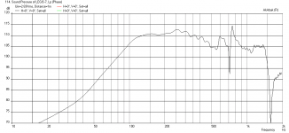
HR sim. vs. measured response (at above mentioned test conditions) at random input power from ~5cm away of each slot (to remove the effect of room). I have not measured the real path lenght yet, I used 270cm at HR. Measurement with a wire (shortest possible path lenght) was 240cm.
I wonder what causes the slight dip at ~29Hz, a leak maybe?
I wonder what causes the slight dip at ~29Hz, a leak maybe?
An externally hosted image should be here but it was not working when we last tested it.
Last edited:
The measurement looks great - very good agreement. The dip at 30Hz is probably room effects even though you are 5cm away it still will be there. Congratulations on coming up with a completely new type of sub woofer. I don't think I have seen anything else like this with push pull and how it is folded. So if you add the mouth extension on via hinged wings it will take it deeper and louder? You can test by aiming output mouth into a corner to approximate the additional expansion.
- Status
- Not open for further replies.
- Home
- Loudspeakers
- Subwoofers
- Study of a Dipole/Cardioid Bass Horn