Hi X,
I should've brought this up earlier. I found quite a few cases in your sims that the cone displacement drops in the lower end. Did you apply any HP filter on them?
It's the opposite of what I've seen in hornresp regularly, and common sense.
Say, under certain frequency that the driver is no longer loaded by the horn (and no chamber in TH), it should run wild, no?
CLS,
Yes, I usually apply a high pass filter (HPF) when I am trying to figure out what the max SPL of the system is. Without a HPF and runaway excursion, you would not be able to get much max SPL without shooting the voicecoil out of the driver. I believe I usually indicate when I apply the HPF (which is almost all the time). When I first set up a system it is usually off so I can see what the inherent response looks like. I tend to use a -24dB/oct Butterworth.
X
If you look in the previous block of code for the PPTP, you will see a block of code for the HPF:
| *** set high pass filter to protect speaker over excursion xmax is 19 mm
Filter 'High Pass' | 4th order Butterworth -24dB/oct, set freq with fo
fo=23.0Hz vo=1.0
{b4=1;
a4=1; a3=2.613126; a2=3.414214; a1=2.613126; a0=1; }
In real world situations many 18" pro-woofers have moderately/highly decreasing compliance when excursion increases. The amount of beating a woofer takes for example in dipole, is in those cases much more than a simulation with static parametres predicts. I have had my 1400W/4ohm pro-amp to clip with a couple of free aired 18N860s with "Bass, I love You". Simulation might predict 2x X-damage at that point 😀. Never used HPF with these in dipole. In home use it's quite easy to design overkill from the start, that doesn't need protection. Healthy over capacity = lower distortion at given listening volume and no HPF introduced group delay.
MiniDSP products (at least Nanodigi) seem to have a maximum of 9ms/~3m delay per channel, little troublesome with TH's. Why do such a limited delay anyway, I see no point... My application should luckily still fit in barely, if I choose the Nanodigi.
MiniDSP products (at least Nanodigi) seem to have a maximum of 9ms/~3m delay per channel, little troublesome with TH's. Why do such a limited delay anyway, I see no point... My application should luckily still fit in barely, if I choose the Nanodigi.
It's a hardware limitation in the 2x4 versions. If you get the 2x8, the delays are much longer - but it costs more. I run into that myself and it is a problem with any system that has a longer than 7.5 ms delay (not 9 ms, at least on 2x4 miniDSP).
Just noticed that tapped pipe could be mixed with front horn for double effect.
Usually (positively tapered) tapped horn does not simulate good with front horn (with long S3-S4 / S4-S5), but for some reason the PPSL tapped pipe likes front horns! I think it's because 1) the woofers are right at the mouth and propably more importantly 2) a pipe loads the woofers uniformly at all frequencies (so the response stays linear even with front horn).
Tapped horn/pipe gives approx. +6dB sensitivity/capacity over direct radiator. Front horn could give another ~6dB = MASSIVE sensitivity. It's basically a front horn that is driven with both sides of the cone by the "PPSL tapped pipe motor". 😀
Darker trace is the front horn version, lighter trace is without. Simulated in 2pi/free field. Front horn (S4-S5) in this simulation is "only" 100cm long and opens to 14000cm2 (compared to normal 25cm long S4-S5 that opens to 4161cm2 like in previous posts). With bigger front horn the gain is greater and/or extends lower.
The easiest way to implement some front horn is to use hinged side walls. They could be closed when not listening.
Usually (positively tapered) tapped horn does not simulate good with front horn (with long S3-S4 / S4-S5), but for some reason the PPSL tapped pipe likes front horns! I think it's because 1) the woofers are right at the mouth and propably more importantly 2) a pipe loads the woofers uniformly at all frequencies (so the response stays linear even with front horn).
Tapped horn/pipe gives approx. +6dB sensitivity/capacity over direct radiator. Front horn could give another ~6dB = MASSIVE sensitivity. It's basically a front horn that is driven with both sides of the cone by the "PPSL tapped pipe motor". 😀
Darker trace is the front horn version, lighter trace is without. Simulated in 2pi/free field. Front horn (S4-S5) in this simulation is "only" 100cm long and opens to 14000cm2 (compared to normal 25cm long S4-S5 that opens to 4161cm2 like in previous posts). With bigger front horn the gain is greater and/or extends lower.
An externally hosted image should be here but it was not working when we last tested it.
The easiest way to implement some front horn is to use hinged side walls. They could be closed when not listening.
An externally hosted image should be here but it was not working when we last tested it.
Nice find! That's what a front horn will do for you 🙂 good idea about the folding wings for the horn - you need that to technically fit in your 1 square meter footprint requirement. Did you try implementing the front horn expansion in AkAbak? Add another segment of waveguide expansion and set the radiator node at the exit of the new segment. That is all there is to adding a front horn.
PPTH with Front Horn
Legis,
I added a front horn with geometry you specified. Here is a before and after result of the sim. There is indeed gain but it is not flat - biased towards the upper end of the bandwidth before the cutoff.
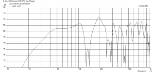
Without Front Horn:
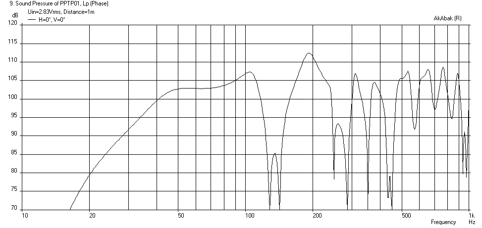
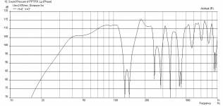
With Front Horn:

Legis,
I added a front horn with geometry you specified. Here is a before and after result of the sim. There is indeed gain but it is not flat - biased towards the upper end of the bandwidth before the cutoff.
Without Front Horn:
With Front Horn:
Attachments
Legis,
I added a front horn with geometry you specified. Here is a before and after result of the sim. There is indeed gain but it is not flat - biased towards the upper end of the bandwidth before the cutoff.
Without Front Horn:
With Front Horn:
Quite good gain though, for the same diaphragm displacement... Around 3db at 20hz and 4-6db 50-100hz(and slightly better anechoic extension)? Did you use HPF? Im not gonna use one...
Last edited:
No HPF
I turned the 19Hz -24dB HPF off:

There is indeed increased bass extension due to longer length provided by the extra 1m long horn extension. The HPF doesn't really affect bass extension - it just reduces group delay from 30ms to 23ms at 37 Hz, and 13.4ms to 10ms at 50 Hz - so may be an important consideration if high SPL is not goal.
I turned the 19Hz -24dB HPF off:
There is indeed increased bass extension due to longer length provided by the extra 1m long horn extension. The HPF doesn't really affect bass extension - it just reduces group delay from 30ms to 23ms at 37 Hz, and 13.4ms to 10ms at 50 Hz - so may be an important consideration if high SPL is not goal.
Attachments

Last edited:
Thanks for the sims, X. The front horn loaded TP's sensitivity matches quite nicely with the 2x Deltalite 2515 midbass (/synergy) horns I intend to make. I hope that a pair of those will be quite an experience to hear/feel even at 20V input.😀
Legis,
You are making a Synergy with a 15in Deltalite? What CD? Those can be tricky but should doable. There are several excel spreadsheets out there for calculating profile. I happen to have an AkAbak sim of a Synergy 😀
You are making a Synergy with a 15in Deltalite? What CD? Those can be tricky but should doable. There are several excel spreadsheets out there for calculating profile. I happen to have an AkAbak sim of a Synergy 😀
Legis,
You are making a Synergy with a 15in Deltalite? What CD? Those can be tricky but should doable. There are several excel spreadsheets out there for calculating profile. I happen to have an AkAbak sim of a Synergy 😀
Yes I intend to try how it works out. Comps are 2" JBL 2446J. XO at 500-550Hz. Horn will look something like this:
An externally hosted image should be here but it was not working when we last tested it.
I will make the comp's vertical transition to horn smoother of course and midwoofer's will have some kind of slots centered at ~17,2cm (1/4 wl) from the throat.
If the comp sounds at least decent in that kind of horn, then I won't have to buy midrange horn. I have my doubts though.🙂
Oh, this is the horn that started this thread - I did not realize it was your Synergy... So you will have a CD at the vertex with a smoother transition to the V-horn? I actually have a model of a B&C DE-250 CD for Akabak and can stick that in the V-horn from post 1. Maybe with a short tansition section to go from 1in x 1in CD throat to the vertex of the V.
Oh, this is the horn that started this thread - I did not realize it was your Synergy... So you will have a CD at the vertex with a smoother transition to the V-horn? I actually have a model of a B&C DE-250 CD for Akabak and can stick that in the V-horn from post 1. Maybe with a short tansition section to go from 1in x 1in CD throat to the vertex of the V.
The idea of synergy came later, "no harm in trying" 😀. Yes I try to make smooth transition so the change in pressure is not so sudden.
You can definitely simulate that, please attach the script also! Propably the biggest difference between post #1's horn and what I currently planned to build, is that the current version does not have any parallel sides.
Last edited:
Legis V-horn Synergy with DE-250
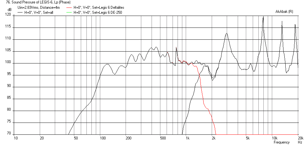
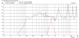
Here is what you get if you add a B&C DE-250 CD feeding a very short 2.5cm long transition duct from the CD throat to a 2.5cm wide x 50 cm tall back vertex. I also added a compression chamber between the Deltalites with an injection port leading from the chamber (formed between driver cone and horn walls) at the same location as before (17.3 cm axial distance). I estimated the chamber volume as 4 liters with a 10 cm dia injection port (or equiv area slot) going through 18mm plywood as the port length. This compression chamber and port increased the mid horn bandwidth into well above 1kHz (vs 500 Hz previously without). This is needed to properly XO with the DE-250 which has a recommended XO point at 1600 Hz. I set the XO freq at 1600 Hz, added 4 ohms of padding to the CD and gave it a 6.8uF high pass shelf to boost upper end response (this can all be done in DSP if run actively).
It is not a bad start given that I threw this together by adding the CD and makeshift transition duct. The CD will appear to have horn "honking" and this can only be solved by having a real horn profile or centerbody phase plug vs. a simple V geometry. A tractrix perhaps? (this may be useful as a point to start a design: http://www.volvotreter.de/downloads/Tractrix_v1.4b.zip )
Here is the Freq Response with 2.83v input at 4 meters away to give space for the mids and highs to integrate (that is some wicked sensitivity there):
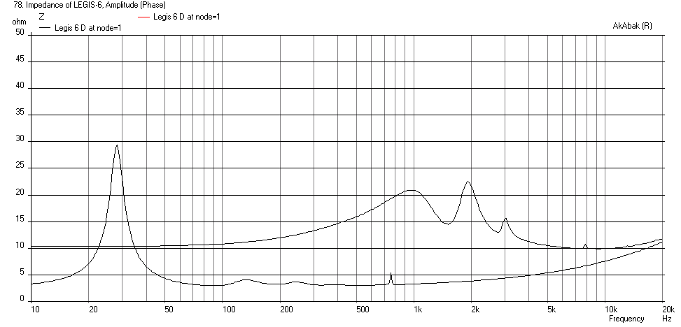
Here is the Impedance:
Here is the code if you want to play with it:
Here is what you get if you add a B&C DE-250 CD feeding a very short 2.5cm long transition duct from the CD throat to a 2.5cm wide x 50 cm tall back vertex. I also added a compression chamber between the Deltalites with an injection port leading from the chamber (formed between driver cone and horn walls) at the same location as before (17.3 cm axial distance). I estimated the chamber volume as 4 liters with a 10 cm dia injection port (or equiv area slot) going through 18mm plywood as the port length. This compression chamber and port increased the mid horn bandwidth into well above 1kHz (vs 500 Hz previously without). This is needed to properly XO with the DE-250 which has a recommended XO point at 1600 Hz. I set the XO freq at 1600 Hz, added 4 ohms of padding to the CD and gave it a 6.8uF high pass shelf to boost upper end response (this can all be done in DSP if run actively).
It is not a bad start given that I threw this together by adding the CD and makeshift transition duct. The CD will appear to have horn "honking" and this can only be solved by having a real horn profile or centerbody phase plug vs. a simple V geometry. A tractrix perhaps? (this may be useful as a point to start a design: http://www.volvotreter.de/downloads/Tractrix_v1.4b.zip )
Here is the Freq Response with 2.83v input at 4 meters away to give space for the mids and highs to integrate (that is some wicked sensitivity there):
Here is the Impedance:
Here is the code if you want to play with it:
Code:
| Model of Legis open back dual driver 1 m x 1m x 50 cm high V-horn with
| Dual Deltalite 15's driving a compression chamber with injection ports
| in a Synergy style layout with a CD feeding vertex for high frequencies
| by xrk971
| July 22, 2014
| File LEGIS-6

System 'Legis 6 Deltalites'

Def_Const

{

| ### input parameters ###

| ### Define exterior physical size of speaker

Width = 1.00  ;   | width at mouth in meters
Height = 0.50 ;   | height of speaker in meters
Depth = 1.00  ;   | depth of speaker from cusp to mouth in meters

Speaker_pos=0.25;  | Speaker height above floor in meters
Dist_wall=2.0;     | Speaker distance from back wall in meters

XO_freq=1600  ;     | XO Freq between Mid and High in Hz
L_tx=2.5*0.01;       | Transition duct between CD throat and main V horn vertex in cm

| Horn geometery

S0=0.0125    ;  |width of vertex in meters (small value)
S1=0.173   ;  |width at driver center assuming 200 mm center to edge distance for driver in meters
L01=0.173  ;  |distance from vertex to driver on centerline cos(30deg)*200mm=173mm
S2=1.00    ;  |width at mouth in meters
L12=0.827  ;  |distance from driver at centerline to mouth in meters

| *** driver comp chamber ***
Vol_driver_chmber=4.0*0.001;  | vol between driver cone and inj port in liters
Dia_inj=5.0 * 0.0254; | Inj port dia inches or equivalent area
Q_ch=0.707;   | Q of driver inj chamber (adjust with stuffin/padding between driver and port)

| ## DE250 Compression Driver params ##

Ree=6.3; |Voice coil resistance [ohm] ......(Re)
Le=0.11e-3; |Voice coil inductance [H] ......(Le)
Bl=9.3; |Motor conversion factor F=Bl*i [Tm]......(BL)
Mms=1.4e-3; |Mechanical mass [kg] ......(Mms)
Rms=.5; |Mechanical resistance [Ns/m] ......(Rms)
Cms=30e-6; |Mechanical compliance [m/N] ......(Cms)
dDi=40e-3; |Diameter centre diaphragm [m] ......(Diam of inner magnet)
dDa=47e-3; |Diameter outer diaphragm [m] ......(Diam of outer chamber)
Hi=1.0e-3; |Eff. height of outer chamber under the ring ......(gap between diaphragm and phase plug)
Ha=4.5e-3; |Eff height of outer chamber under the ring ......(Averaged height of annular chamber)
ds=0.20e-3; |Slit between voice coil and magnet ........(Annular gap between magnet and voice coil former)
ls=11e-3;  |Length of voice coil path .......(Length of annular gap)

}

Def_Driver  'Deltalite15'  | Eminence Model Delatalite II 15  4.8 mm xmax, 99.2dB, Qts 0.38
  SD=856.3cm2   |Piston
  fs=42Hz
  Mms=72g
  Qms=4.56
  Qes=0.41
  Re=5.29ohm
  Le=1.15mH
  Bl=15.7Tm
  Vas=204L


| Speaker with horn axis CL at Speaker_pos above floor and Dist_wall away from back wall
Def_Reflector  HorizEdge
Bottom={Speaker_pos}  Top={Dist_wall+Depth}
AbsorbCoeff=0.3
HAngle=0  VAngle=0


Filter 'HighPass' |Highpass filter -12dB/oct BW
fo=95Hz vo=1
{b2=1;
a2=1; a1=1.414214; a0=1; }

| *** Cross-over (XO) frequency from Mids to Highs  ***
Filter    'Low Pass'  | 4th order Butterworth Low Pass -24dB/oct set crossover freq at 2500 Hz
    fo={XO_freq}  vo=1.0
    {b0=1;
     a4=1;  a3=2.613126;  a2=3.414214;  a1=2.613126;  a0=1; }


| Define driver to be used and wired in parallel (left driver when viewed from front
Driver Def='Deltalite15' 'Driver 1'
Node=1=0=111=201

| Right driver when viewed from front
Driver Def='Deltalite15' 'Driver 2'
Node=1=0=112=202

| *** option to put chambers with ducts leading to horn injection point ***
Enclosure  'Driver Chamber 1'  Node=111
Vb={Vol_driver_chmber}  Qb/fo={Q_ch}  Lb=1in  | keep chamber very flat - circa 1 in from cone to port

| *** duct from driver 1 compression chamber to horn injection point ***
Duct    'Inject Port 1'  Node=111=11
    dD={Dia_inj}  Len=0.719in | Thickness of wall plywood

Enclosure  'Driver Chamber 2'  Node=112
Vb={Vol_driver_chmber}  Qb/fo={Q_ch}  Lb=1in

| *** duct from driver 2 compression chamber to horn injection point ***
Duct    'Inject Port 1'  Node=112=11
    dD={Dia_inj}  Len=0.719in  | Thickness of wall plywood

| Backside of drivers are radiators angled at 30 deg back - left driver angled left back
Radiator  'Rear_Rad1'  Def='Driver 1'    Node=201
    x=-0.173m  y=0  z=-0.827m  HAngle=-30  VAngle=0
    WEdge={Width/2}  Hedge={Height/2}  Reflection
Label=10

| Right driver back radiator angled back right
Radiator  'Rear_Rad2'  Def='Driver 2'    Node=202
    x=0.173m  y=0  z=-0.827m  HAngle=30  VAngle=0
    WEdge={Width/2}  Hedge={Height/2}  Reflection
Label=20

| ### HORN WAVEGUIDE

Waveguide 'Horn Seg 1'  | From vertex to driver at node=11 (both drivers excite node 11
Node=10=11
STh={S0*Height}
SMo={S1*Height}
Conical
Len={L01}

Waveguide 'Horn Seg 2'  | From driver injection point to mouth
Node=11=12
STh={S1*Height}
SMo={S2*Height}
Conical
Len={L12}

| ### Main horn mouth radiator
Radiator  'Horn Mouth'  Def='Horn Seg 2'    Node=12
    x=0  y=0  z=0  HAngle=0  VAngle=0
    WEdge={Width/2}  Hedge={Height/2}  Reflection
Label=20


| ****
| **** New system for CD Portion with same waveguide ***
| ****

System 'Legis 6 DE-250'

| *** XO from low freq to high high pass ***
Filter    'High Pass'  | 4th order Butterworth -24dB/oct  set XO freq at 1500 Hz
    fo={XO_freq}  vo=1.0
    {b4=1;
     a4=1;  a3=2.613126;  a2=3.414214;  a1=2.613126;  a0=1;  }

| *** padding resisitor and boosting HP shelf cap (can all be done in DSP EQ if desired) ***
Resistor    'CDPad'  Node=1=350  R=4ohm  | Padding resistor to attenuate CD relative to woofer
Capacitor   'CDHP'   Node=1=350  C=6.8uF  | High pass shelf capacitor


| Model of B&C DE250 Compression driver

|Voice coil (frequency-non-linear resistance and reactance)
Impedance 'Ze'
Node=350=502
Z={ Ree*(1 + f/25e3) + j*(w*Le)^0.5; }
|.......(f/? , w*Le^?)

|Motor
Gyrator 'Gy1'
Node=502=0=503=504
Bl={Bl}

|Reverse side with enclosure
Coupler Node=504=0=100
dD={dDa}
Enclosure 'Eb' Node=100
Vb=5cm3
Qb/fo=0.0008 | .......(Vb , Qb/fo)

|Mechanical part (Mms frequency depending, cut-off at ? kHz)
Impedance 'Zms' Node=503=505
Z={ wo=2*pi*15000;
Zms=Rms + j*(w*Mms/(1 + w/wo) - 1/(w*Cms)) } | ......(2*pi*?)

|Outer diaphragm (ring) with cavity
Coupler
Node=505=506=200
SD={ pi*(sqr(dDa/2)-sqr(dDi/2)) }
Enclosure 'Efo'
Node=200
Vb={ Ha*pi*(sqr(dDa/2)-sqr(dDi/2))}

|Centre diaphragm with compression chamber
Coupler Node=506=0=300
dD={dDi}
Enclosure 'Efi'
Node=300
Vb={ SD=pi*sqr(dDi/2);
Vb=SD*Hi }

|Voice coil tunnel between outer ring cavity and compression chamber
Duct 'Dvp'
Node=200=300
SD={ U=pi*dDi;
SD=U*ds }
Len={ ls }
QD/fo=0.003 | .......(QD/fo)

|Horn inside compression driver
Waveguide 'Wpp'
Node=300=10
dTh=2.32cm
dMo=1in
Len=3.0cm
Conical
|......dTh, dMo, Len

| Couple CD throat exit to node=10 of main waveguide internal horn inside Beta 10CX

| *** Transition duct from CD to main V horn ***

Waveguide 'Horn Seg 0'  | From CD throat to imternal horn mouth node=10=11
Node=10=11
    STh=4.46cm2  | area is exit of CD
    SMo={S0*Height}  | Set same as vertex area
    Len={L_tx}       | Set length of transition from CD throat to V horn vertex
    Conical

| *** Same V horn as above system for Deltalites ***

Waveguide 'Horn Seg 1'  | From vertex to driver at node=11 (both drivers excite node 11
Node=10=11
STh={S0*Height}
SMo={S1*Height}
Len={L01}
Conical

Waveguide 'Horn Seg 2'  | From driver injection point to mouth
Node=11=12
STh={S1*Height}
SMo={S2*Height}
Len={L12}
Conical

| ### Main horn mouth radiator
Radiator  'Horn Mouth'  Def='Horn Seg 2'    Node=12
    x=0  y=0  z=0  HAngle=0  VAngle=0
    WEdge={Width/2}  Hedge={Height/2}  Reflection
Label=30
Attachments

It is not a bad start given that I threw this together by adding the CD and makeshift transition duct. The CD will appear to have horn "honking" and this can only be solved by having a real horn profile or centerbody phase plug vs. a simple V geometry. A tractrix perhaps? (this may be useful as a point to start a design: http://www.volvotreter.de/downloads/Tractrix_v1.4b.zip )
Thanks, that is a good start. Those resonances are ought to be standing waves between the parallel walls used in the sim. If the horn is made 40-45cm tall at the other throat/apex and 60cm at the mouth (like in the last picture I posted), those resonances might be almost completely gone? Could you sim a horn geometry like in the last picture I posted that has no parallel walls?
I wonder if the fast vertical transition is responsible of some artifacts in the plot?
It's not due to parallel walls as AkAbak is a lumped element model and does not have that level of detail. That is really the axial horn expansion profile that controls those resonances - mostly the abrupt and straight wall profile leading to the mouth. I tried making the transition longer up to 25cm and it did not improve things. Adding a secondary expansion like Danley uses in his Synergy can help a lot as well as making a curved profile with a round over at the mouth.
It's not due to parallel walls as AkAbak is a lumped element model and does not have that level of detail. That is really the axial horn expansion profile that controls those resonances - mostly the abrupt and straight wall profile leading to the mouth. I tried making the transition longer up to 25cm and it did not improve things. Adding a secondary expansion like Danley uses in his Synergy can help a lot as well as making a curved profile with a round over at the mouth.
Ok, thanks for the reminder, I forgot that about Akabak.
Hmm, another idea for DSP users: put the mid horn and super tweeter horn inside/at the mouth of the midbass horn like this:
An externally hosted image should be here but it was not working when we last tested it.
Maybe this kind of tri/-coaxial horn arrangement could be more viable than real Synergy horn from scratch, for those without the ability to make more sophisticated horn geometries (curved or multi segment conical).
The radiation pattern would not be as uniform, and the time aligment would need DSP, but the source of sound would propably seem almost like one point source. Also the midwoofers would not modulate the comp's membrane nearly as much as they would if attached in the same horn (which can make quite a difference near the lower XO-point of the comp at high SPLs).
This would also allow midwoofers to be installed in push-pull configuration (if that does not screw too much the response near the upper XO point), what the synergy config does not allow.
I actually like this idea compared to synergy.
Legis,Hmm, another idea for DSP users: put the mid horn and super tweeter horn inside/at the mouth of the midbass horn like this:
Maybe this kind of tri/-coaxial horn arrangement could be more viable than real Synergy horn from scratch, for those without the ability to make more sophisticated horn geometries (curved or multi segment conical).
The radiation pattern would not be as uniform, and the time aligment would need DSP, but the source of sound would propably seem almost like one point source. Also the midwoofers would not modulate the comp's membrane nearly as much as they would if attached in the same horn (which can make quite a difference near the lower XO-point of the comp at high SPLs).
I actually like this idea compared to synergy.
I actually built dozens of nested horn cabinets back in 1992 called the Maltese horn. The Maltese used a conical expansion HF horn inside the mid, mid inside the low, and though they did approximate a point source, the Synergy design simply works far better for all the reasons you mentioned and many more.
Your speculation that the the midwoofers would not modulate the compression driver's diaphragm as much as they would if attached in the same horn is unfounded, modulation is not a problem in either design.
A Synergy design is also three times easier to build than a 3 way nested horn.
Art
- Status
- Not open for further replies.
- Home
- Loudspeakers
- Subwoofers
- Study of a Dipole/Cardioid Bass Horn