I was wrong on my comment that I couldn't hang a pot from my output, as long as the variable pin is not connected to it.
But I wonder (and I asked TI about it) how do you reference the 49600 to VCC/2, as I'm using a single supply.
But I wonder (and I asked TI about it) how do you reference the 49600 to VCC/2, as I'm using a single supply.
I was wrong on my comment that I couldn't hang a pot from my output, as long as the variable pin is not connected to it.
You can use a low value pot, after the output cap. It's a poor design though.
You're driving it with an op amp, right? Just use a standard VCC/2 bias arrangement for a single ended op amp circuit. The op amp will bias the 49600.But I wonder (and I asked TI about it) how do you reference the 49600 to VCC/2, as I'm using a single supply.
I just got done doing this, and it works fine.
You can use a low value pot, after the output cap. It's a poor design though.
Well, I have to pick the level after my final stage. That is because I will compare it with my return to where I'm sending it to.
There's already a loading resistor after the output blocking cap, and it's there were I'm picking my headphone input. Where's the poor design in that?
You're driving it with an op amp, right? Just use a standard VCC/2 bias arrangement for a single ended op amp circuit. The op amp will bias the 49600.
I just got done doing this, and it works fine.
The 49600 has no inverting and non-inverting inputs, only one input.
What TI proposes, on their forum, is for me to create a Vcc/2 reference and use that as ground for everything, float it completely from chassis ground. I don't think it's practical.
There's already a loading resistor after the output blocking cap, and it's there were I'm picking my headphone input. Where's the poor design in that?
Are you going to put it in series with the headphones? That is poor design, but it's how those in line volume controls work.
The 49600 has no inverting and non-inverting inputs, only one input.
What TI proposes, on their forum, is for me to create a Vcc/2 reference and use that as ground for everything, float it completely from chassis ground. I don't think it's practical.
So you're using the buffer as a stand alone? You can still use a VCC splitter circuit with an isolation resistor for each channel. DC performance won't be the best, but I guess it doesn't matter if you're using an output cap.
You don't need a floating ground for this circuit. Ground the input signal and headphone output ground to V-. Input must be capacitor coupled. Common mode rejection ratio may be compromised compared to a split supply circuit.
Maximum performance is obtained with an op amp in the circuit, and overall global feedback.
You should be able to do what you want to do with good results, if implemented and sorted correctly.
Last edited:
Are you going to put it in series with the headphones? That is poor design, but it's how those in line volume controls work.
No, I have my main preamp output, which has a blocking capacitor and 10K resistor to ground. That's my main output.
From that I'm picking the input to my headphone and my VU-meter, so I can measure exactly what I'm getting.
My head amp is an inverting 10:1 NJM 4556, and there's a 50K trimpot at the input of an LM3915 to adjust the 0dB LED when I finish things up. That trimpot will probably be replaced by fixed resistors once level is set.
So that is loading my main output.
So you're using the buffer as a stand alone? You can still use a VCC splitter circuit with an isolation resistor for each channel. DC performance won't be the best, but I guess it doesn't matter if you're using an output cap.
You don't need a floating ground for this circuit. Ground the input signal and headphone output ground to V-. Input must be capacitor coupled. Common mode rejection ratio may be compromised compared to a split supply circuit.
Maximum performance is obtained with an op amp in the circuit, and overall global feedback.
You should be able to do what you want to do with good results, if implemented and sorted correctly.
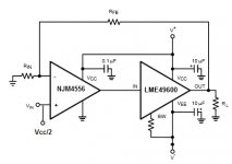
Yes, I would be using a global feedback combo with the NJM4556 as 1st stage and the 49600 as second. But I don't know how to reference it to Vcc/2. The output ground has to be chassis ground, not Vcc/2, and I don't know if it's possible with this chip.
My schematic is not complete, as I only referenced the 1st stage to Vcc/2. The second it's not and I don't have -V.
Attachments
Last edited:
My schematic is not complete, as I only referenced the 1st stage to Vcc/2. The second it's not and I don't have -V.
You do not have to reference the second stage. The first stage will bias it.
My circuit is single ended and is biased like that.
Why inverting? You can make it non-inverting too.
The output ground has to be chassis ground, not Vcc/2, and I don't know if it's possible with this chip
Capacitor coupled output, "grounded" to V- will work.
Also the input must be capacitor coupled.
Last edited:
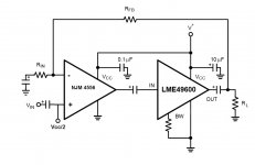
Something like this then?
The feedback must be taken from the DC side of the output capacitor. This ensures that the output will sit at VCC/2.
Other than that, you got it.
The VCC/2 circuit can be two 100K resistors in series, with a 100K resistor feeding the non-inverting input from the junction of the two splitter resistors. This node where the three resistors connect should be shunted to ground with an electrolytic capacitor. You can control turn-on time (for a "soft start") by varying the value of the capacitor. Try values of 1 to 5 uF.
Last edited:
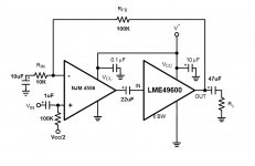
OK, please check if the capacitors values I included now should be fine, particularly the one between the chips and the output cap.
I was thinking of adding a 49.9 series resistor after the output capacitor, along with 1N4148 protection diodes to Vcc and ground. Some claim that protection should be right at the output of the chip, others put it after the capacitor.
As you can see I left BW unconnected to limit bandwidth, according to the datasheet.
Nice touch about using 4.7uF uF on Vcc/2 to soft start the head amp, as it should protect users from eventual thuds on their ears.
One thing I didn't realize, and correct me if I am wrong, is that if I use the same Vcc/2 generator with both channels, I'm actually linking both outputs through the 100K resistors. Would that mix the channels somehow?
Attachments
Why did you put a capacitor between the op amp and the buffer? That totally, 100% defeats the whole point of biasing the input. Lose that capacitor.
On what logic did you choose your feedback resistors? That are way, way too big. Reduce them by a factor of ten and increase the feedback capacitor to 100 uF.
How did you calculate your output capacitor? What impedance are your headphones? For low impedance cans the capacitor is way too small. 470 uF is barely big enough for 32 ohm cans. 1000 uF is better. And add a bleeder resistor from output to ground.
Will it be battery operated? Leaving the bandwidth pin open will insure minimum quiescent current, and minimum bandwidth too. I connected mine directly to ground but this might not be practical on a battery powered circuit.
I was thinking of adding a 49.9 series resistor after the output capacitor, along with 1N4148 protection diodes to Vcc and ground. Some claim that protection should be right at the output of the chip, others put it after the capacitor.
Skip the resistor, but use the diodes. They belong right after the chip. They prevent the charged voltage on the capacitor from exceeding power supply voltage on shutdown.
As you can see I left BW unconnected to limit bandwidth, according to the datasheet.
You want the bandwidth of the output device to be much greater than the driver. The bandwidth pin also controls the output stage quiescent current.
It will most likely be fine with the pin left open. But as the designer it is up to you to juggle the parameters.
One thing I didn't realize, and correct me if I am wrong, is that if I use the same Vcc/2 generator with both channels, I'm actually linking both outputs through the 100K resistors. Would that mix the channels somehow
Not if you use the electrolytic capacitor to shunt the VCC/2 divider. 😉
I would not depend on this to set the input impedance though. If you are putting a pot on the input (before the input cap) then you are fine. Otherwise shunt the input (before the capacitor) with a resistor from 10-47K.
particularly the one between the chips
I'm interested in the logic you used to determine why you need a cap there. Did the guys on the TI forum tell you that? They're 100% wrong then. The circuit will absolutely not DC bias correctly with that capacitor there.
OK, I wasn't sure about the blocking capacitor between the ICs, as I would certainly have half my DC voltage at the output. Would that voltage bias the input?
For the second question, my intention was exactly the opposite to yours: larger resistors, small capacitors, film if possible.
For the third, yes, I did guess the output capacitor should be ten times what I put, but I wonder how do you compute that. What formula and values to use?
And fourth, yes, it will always be battery operated. I do prefer minimum quiescent current, and I don't see how 110MHz is not more than enough BW. What benefit from connecting the BW pin to ground?
OK, I wasn't sure about the blocking capacitor between the ICs, as I would certainly have half my DC voltage at the output. Would that voltage bias the input?
The input biases the output; not the other way around. The op amp + buffer for all practical purposes is an op amp.
Lose the capacitor.
For the second question, my intention was exactly the opposite to yours: larger resistors, small capacitors, film if possible.
Why? Don't you understand resistor noise? Bigger resistor = more noise. In fact the noise generated increases with the square of the resistor.
This is why you see well sorted circuits with small value resistors in the feedback loop. Any noise generated by the resistor is injected directly into the inverting input.
Your circuit will work but you're leaving a lot of performance on the table with those choices of resistors. I assume that you'll be assembling a prototype. You can find out for yourself then.
For the third, yes, I did guess the output capacitor should be ten times what I put, but I wonder how do you compute that. What formula and values to use?
This is really basic stuff.
-3 dB cutoff = 1/ (2*pi*R*C) C is in farads; R is load resistance. A scientific notation calculator makes these calculations simple.
And fourth, yes, it will always be battery operated. I do prefer minimum quiescent current, and I don't see how 110MHz is not more than enough BW. What benefit from connecting the BW pin to ground?
It depends on the bandwidth of the op amp. For most common op amps 110 MHz is fine. If you look at the datasheet headphone amp circuit, there are recommendations for an optional Miller capacitor. You might have to go that route. Alternatively you could adjust the bandwidth with the bandwidth pin.
The benefit for a headphone amp is increasing quiescent current. If you're using a power supply that plugs into the wall then there is no reason not to ground the pin. However for battery operation it makes sense to leave it open, if stability is OK.
Regarding the resistors, I used 4.7K and 3K in the feedback loop. I employed Vishay-Dale CMF55 series low noise, high bandwidth resistors. This is probably extreme overkill for such low values, but using low noise resistors (like the CMF55 there's no better resistor for audio that doesn't cost 50 times more as far as I know) will afford you a lot of leeway on resistor values. Make sure that any resistors you choose for this application are low inductance types; any nonlinearities here will translate directly into distortion.
If you keep the resistor values low (ideally below 10K) then you will probably get excellent performance from ordinary carbon resistors. My amp has extremely low noise; completely inaudible with 32 ohm 110 dB/mW headphones. It is also very neutral and dynamic.
You won't be disappointed if you carefully sort the design and weigh the tradeoffs. It will be far better than any Cmoy, except for battery life.
Will you be using a rechargeable battery? Some commercial portable amps charge directly off the USB port. You can charge more that 5 volts by using a voltage doubler.
First of all, this is the last stage of a professional portable mic preamp. Where you listen to things after they were amplified. Noise is really a problem in low noise stages, where's it's justified because of the low audio levels and gain chains.
Second, I think it was more than proven that capacitor distortion, which is greatest in most ceramics, many tantalums and many electrolytics, is a major problem. In the choice between better distortion and slightly higher noise, when it doesn't involve low level audio, I will always prefer film caps if I can afford them, in price or space. That's an easy decision.
At the input of this preamp, which uses a THAT 1510 chip, where most people used two back to back electrolytics, I choose 1uF film caps. Some time ago I did try, while listening, all electrolytics I could find, even the ones recommended by the designer, and a simple Siemens 1uF Polyester destroyed them all in quality and else.
This project will all be done with SMD 0805 1% resistors and 0.1% on some specific places. Only the low-cut filter capacitors will be through hole, because film SMDs get affected by industrial soldering.
And I do understand that everything is a compromise, in this case between size, price and quality.
Now about the capacitor value. For a 75ohm headphone and a 470uF capacitor I'm getting a -3dB frequency of 4.52Hz. I would be more than satisfied with 10Hz, which would imply a 220uF capacitor, or even 20Hz, that would mean 100uF.
Yes, a 47uF would mean a 40Hz -3dB, but my lowest interstage cut would be 33Hz, with my higher being 120Hz. So even 100uF would be more than enough.
This preamp is mainly addressing dialogue recording, and I talked to several pro location film audio people, where all pointed at 120Hz as the critical point to "clean up" most room-tone problems.
Now, the reason for me using or not an LME is if I can drive even higher impedance headsets, like 200 or 600 ohms. But my first tests will be carried out just with the NJM4556, just by itself.
BTW, I remember an article by Erno Borbely on why lower value resistors were justified on a power amp gain.
But he also mentioned the price you had to pay for that was using high value electrolytics. So he went for DC servo designs or full DC designs, no capacitor, which needed sophisticated ways to have no DC drifts and/or alarms to protect you, usually with relay controlled protection.
But he also mentioned the price you had to pay for that was using high value electrolytics. So he went for DC servo designs or full DC designs, no capacitor, which needed sophisticated ways to have no DC drifts and/or alarms to protect you, usually with relay controlled protection.
First of all, this is the last stage of a professional portable mic preamp. Where you listen to things after they were amplified. Noise is really a problem in low noise stages, where's it's justified because of the low audio levels and gain chains.
Which circuit? You only posted one or two that would actually work.
Di the "professional" circuit use those resistor values? What kind of resistors did they use?
Lower value resistors produce lower noise, and that's a fact. You can test different values and see for yourself whether it makes an appreciable difference. Also higher resistance values will be more affected by the inductance of the resistor and the rest of the circuit around it.
Second, I think it was more than proven that capacitor distortion, which is greatest in most ceramics, many tantalums and many electrolytics, is a major problem. In the choice between better distortion and slightly higher noise, when it doesn't involve low level audio, I will always prefer film caps if I can afford them, in price or space. That's an easy decision.
It's only a major problem if your design is marginal. A properly sized electrolytic used as a coupling capacitor or DC blocking capacitor in a feedback network will produce negligible distortion. If it is small enough to intrude on the audio range, then yes an electrolytic will definitely introduce more distortion than a film capacitor.
At the input of this preamp, which uses a THAT 1510 chip, where most people used two back to back electrolytics, I choose 1uF film caps. Some time ago I did try, while listening, all electrolytics I could find, even the ones recommended by the designer, and a simple Siemens 1uF Polyester destroyed them all in quality and else.
If the difference was clearly audible, then the capacitor was probably too small. You did not state what impedance the capacitor was driving. That makes a huge difference.
It is still a good idea to configure your circuit so that film capacitors are practical for some applications like input coupling capacitors. It is hardly practical to use them in all audio applications, though. For applications where only an electrolytic is practical, you can always bypass them with a nice film capacitor.
You should read Cyril Bateman's paper on capacitor distortion. It will help you separate folklore from fact.
Now about the capacitor value. For a 75ohm headphone and a 470uF capacitor I'm getting a -3dB frequency of 4.52Hz. I would be more than satisfied with 10Hz, which would imply a 220uF capacitor, or even 20Hz, that would mean 100uF.
Yes, a 47uF would mean a 40Hz -3dB, but my lowest interstage cut would be 33Hz, with my higher being 120Hz. So even 100uF would be more than enough.
You do not want the -3 dB point inside the audible range. -3 dB is a lot and also comes with significant phase distortion and also that electrolytic distortion that you seem so keen to avoid.
If I'm shooting for a low frequency cutoff of let's say 20 Hz, I calculate for -3 dB at 2 Hz. This ensures no sonic intrusion in the audio range; the response will be down 0.1 dB at 20 Hz with minimal phase shift.
So by your calculations, a 10 Hz cutoff would impinge on the audio range all the way up to 100 Hz.
I hope all this helps you understand the juggling act of designing practical circuits.
First of all I'm not such a fan of Bateman's paper, where his main conclusion, if I remember well, were that the best thing was to use two back-to-back bipolars. Sorry, I don't buy that and I haven't seen any schematic where it was implemented, or anyone that claimed a better audio quality by using them.
Second, neither do I buy the "magic" the Black Gate capacitors seemed to bring, even if they are not made any more.
Even if I haven't made any serious tests on subjective audio comparisons on passive parts lately, and this is my first experience with SMD, some rules seem to apply.
Higher voltage capacitors in general are recommended over low voltage, even if your supply is low voltage and also as interstage. No "audiophile" parts though.
The only stage I wished to discuss here was the headphone amp, not the rest of the circuit. Particularly because I'm using a different path from what other designers prefer, not using DC-DC supplies and all that.
But I did discuss all the other matters extensively with THAT's support team, which differed on several angles with what the Pro Audio Design forum recommended. There you're supposed to find more people talking about pro audio applications, what is what this project is. But on some cases it wasn't really so.
The reason I came to this forum, where I used to be helped and help on audio DIY projects over many years, is that things got stuck on the other forum. Neither was I too happy with the "official" formula for pro equipment, like on the DC-DC recipe I mentioned.
About the resistors you asked, no specific types were mentioned. Except being precision types. The noise question was never raised, except on the input stage, which I did mention and where I do think is more critical.
If you look at the THAT 1510 datasheet, where there's a suggested circuit, you will find two large capacitors at the input, which I replaced with a smaller film type.
About my tests, which were made with an SSM2017 circuit, designed by Walt Jung, the recommended Panasonic capacitors sounded much worse than Siemens electrolytics, same value and all 100v parts, and they were all inferior to 1uF 63v film types.
For me is trade off, like I said before, in the matter slightly more noise with less distortion introduced by electrolytic's dielectric. This time I will have to use many eletrolytics, because I don't have the space or the budget to use film types.
But on my output stage, which was inverting, I could get away with film caps, working as the low cut filters before that stage. My gain resistors are high, according to your concepts, 22K/220K.
My "flat" low frequency cutoff is around 50-60Hz, but I will again try other values, particularly on the prototypes and on the field tests several pro location recordists will do on these units.
But our discussion was to be centered around the headphone amp, and on that example case I introduced the same values from Walt Jung's book. WJ has an ear for sound too, and he used exactly those values on his single supply non-inverting suggestion.
Of course he always tries to use no caps at all, with low offset part or with DC servos. But he does prefer a film if he can use it.
I imagine we may be hours here talking over this, separating folklore from fact, as you called it. It won't help too much.
Last edited:
First of all I'm not such a fan of Bateman's paper, where his main conclusion, if I remember well, were that the best thing was to use two back-to-back bipolars. Sorry, I don't buy that and I haven't seen any schematic where it was implemented, or anyone that claimed a better audio quality by using them.
Bateman was referring to non-polarized applications and he concluded that non-polarized electrolytics were the best electrolytic for the application. Non-polarized electrolytics are basically two anodes without a cathode.
But your application is not non-polarized. Bateman concluded that a biased polar electrolytic was the lowest distortion configuration for electrolytic application.
Finally, Bateman did actual empirical tests and showed his results. Take a second look.
Second, neither do I buy the "magic" the Black Gate capacitors seemed to bring, even if they are not made any more.
Neither do I. I keep stressing proper application, which includes designing for the best performance of the parts you intend to use.
Even if I haven't made any serious tests on subjective audio comparisons on passive parts lately, and this is my first experience with SMD, some rules seem to apply.
Higher voltage capacitors in general are recommended over low voltage, even if your supply is low voltage and also as interstage. No "audiophile" parts though.
You're correct about using higher voltage capacitors.
About the resistors you asked, no specific types were mentioned. Except being precision types. The noise question was never raised, except on the input stage, which I did mention and where I do think is more critical.
I already covered this in detail. Low noise resistors can make a difference in some circuits. Although I used them, it is not necessary for this application.
But it is a fact that any noise generated in the feedback loop will be amplified.
If you look at the THAT 1510 datasheet, where there's a suggested circuit, you will find two large capacitors at the input, which I replaced with a smaller film type.
That's fine, as long as you calculated the pole and are satisfied with the result.
But our discussion was to be centered around the headphone amp, and on that example case I introduced the same values from Walt Jung's book. WJ has an ear for sound too, and he used exactly those values on his single supply non-inverting suggestion.
Walt Jung talks about resistor noise extensively in his work.
Resistor choice is a tradeoff like everything else. Larger resistors means smaller capacitors, which is a practical matter.
Of course he always tries to use no caps at all, with low offset part or with DC servos. But he does prefer a film if he can use it
Fewer caps is always better. Single ended designs can't avoid caps.
I imagine we may be hours here talking over this, separating folklore from fact, as you called it. It won't help too much.
I just spent two months sorting an amplifier very similar to yours. I left nothing to chance.
I thought you might find my advice relevant.
To start with, and not to leave any doubts, I do find your advice more than relevant. I am very grateful for it. Be sure of that.
The other questions are relative too. I have spent many weeks discussing these matters in the Pro Audio Forum, and if you don't have as much knowledge in electronics as they have, then you are not interesting to them and treat you poorly.
As I am a bit callous to such things I kept moving on, in spite what they said. The main reason for this was that I had THAT's support behind me, particularly one guy there that helped me a lot on the design for my limiter, which at Pro Audio were very shy in helping with.
I had to redesign this project from what it originally was, because it went over budget. So I had to cut the limiter and pick lower priced parts. Also eliminated the balanced output. But I don't think I sacrificed that much, if any, except for the limiter, which we might bring back or try an alternate chip limiter by NJM, if we can make it work.
For the headphone I'm trying to extract from it as much as possible, though I'm sure there will be heads I won't be able to drive. Hopefully the ones between 25-75 ohms will all be. Let's see. As I said, for now only with a single 4556, with no buffer or output boost. Being the prototype, there will be time to change that.
- Status
- Not open for further replies.
- Home
- Amplifiers
- Headphone Systems
- Portable headphone amp