I do want your project to be a success. I realize that while your circuit is very similar to mine, your objectives are different.
I'm trying to give you something to work with. None of those hot shots at the "pro audio" forum could provide you with a correctly biased, working schematic. I was able to point out what wouldn't work and why, right away.
When it comes to capacitors, there is a whole lot of BS out there. I hope I impressed upon you how to properly implement electrolytic capacitors in an audio circuit. Many, many schematics out there on the web, as well as manufacturer's datasheets and even commercial equipment, do not in fact implement them correctly.
Size is a big priority for your project. This means bigger resistors and smaller capacitors. It's up to you to juggle that. I hope I gave you some direction.
Build that prototype and report back. If you properly sort the prototype, then the buffered version will only work better.
Are you going to solder the heatsink tab of the buffer to the board? There's a whole song and dance involved with that; it involves baking the chips to 250 degrees and then soldering them to the board. The package is really designed for wave soldering. The 49960 comes with instructions and little humidity sensing cards to get the baking and soldering correct. Ask me before you open the package; you're not supposed to open it before 48 hours of baking and soldering it. Of course, you have to open the package to read the instructions and learn this.
Thanks a lot for your advice.
To start with I tell you that I will use a higher value capacitor at the head amp output, and I will try both 220uF and 470uF.
The first version will be just the 4556, without any buffer. Let's see how much it can handle just by itself.
This will quite likely be my main output, high-pass filter included.
Attachments
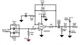
What's the purpose of that high pass filter? You have a choice of 120 Hz or 20 Hz. I don't get your objectives.
You still have no DC blocking on the input. Are we still talking about a single ended amplifier?
R119, R120, plus 100 ohms - what is the purpose of all the resistors? What impedance phones do you intend to drive?
Z109, Z110 - why in the world did you put them there? What purpose do they serve there?
R118 - why such a high value? What is the your purpose for R118?
Where are you getting these circuits anyway?
The filter choices came from consulting my professional location audio friends, and a friend of mine that builds high quality speakers. The objective is using this preamp for film location audio.
What input DC blocking are you talking about? The filter is my DC blocking.
Yes, this is still a single ended amp.
This is not the headphone amp, as I specified. This is my main preamp output. And you do need protection diodes when switching to the world outside. Remember I may find 48v phantom voltages out there.
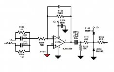
This preamp design more or less follows Walt Jung suggestion from his book, for a single supply non-inverting stage. Until now I was using an inverting stage for this, and it worked flawlessly. But I decided to try with a non-inverting one, taking some precautions, like WJ suggested, like the feedback capacitor being larger than the larger input cap I was using.
What input DC blocking are you talking about? The filter is my DC blocking.
Yes, this is still a single ended amp.
This is not the headphone amp, as I specified. This is my main preamp output. And you do need protection diodes when switching to the world outside. Remember I may find 48v phantom voltages out there.
This preamp design more or less follows Walt Jung suggestion from his book, for a single supply non-inverting stage. Until now I was using an inverting stage for this, and it worked flawlessly. But I decided to try with a non-inverting one, taking some precautions, like WJ suggested, like the feedback capacitor being larger than the larger input cap I was using.
The filter choices came from consulting my professional location audio friends, and a friend of mine that builds high quality speakers. The objective is using this preamp for film location audio.
Your "professional location audio" friends recommended 120 Hz -3 dB cutoff frequency?
Are your "professional location audio friends" electrical engineers?
What input DC blocking are you talking about? The filter is my DC blocking.
No, it's not a DC blocking circuit at all. You have resistors in parallel with the capacitors. Resistors pass DC!
Your filter is not a high pass filter as you apparently intend; it is a shelf filter. But the capacitors form a high pass filter with R116. Is this your intention?
And I see you are still depending on R116 to set your input impedance. As I already said, this is not optimal.
This is not the headphone amp, as I specified. This is my main preamp output.
Well pork me in a goat's bum. All this time I was trying to help you with a simple buffered headphone amplifier.
Are you trying to make a fool out of me? Are you one of those slayers of logic; a purveyor of intellectual dishonesty and duplicity? If so I will cease to waste any more time trying to help you.
You're welcome.
Your "professional location audio" friends recommended 120 Hz -3 dB cutoff frequency?
Are your "professional location audio friends" electrical engineers?
First of all, I tend to trust empirical use more than theoretical use, particularly if if comes from experienced sound engineers. The question was whether to cut at 150Hz, like many mixers do, and I decided to try what my friend suggested. As there will be field tests of all this, that might change.
About the "flat" filter, my other friend designs filters for a living with his speakers, so he advised around 20Hz @ 3dB, so there we go.
No, it's not a DC blocking circuit at all. You have resistors in parallel with the capacitors. Resistors pass DC!
Your filter is not a high pass filter as you apparently intend; it is a shelf filter. But the capacitors form a high pass filter with R116. Is this your intention?
Of course that's my intention. R116 was computed so that I could get to the cut points I wanted.
This very filter circuit was used, always on this single supply design, and checked by THAT support engineers themselves, when I was still using a limiter stage, and I had put an electrolytic capacitor after the filter. They suggested to use the filter itself as input, no DC blocking capacitor.
And I see you are still depending on R116 to set your input impedance. As I already said, this is not optimal.
How would you set your impedance then?
Well pork me in a goat's bum. All this time I was trying to help you with a simple buffered headphone amplifier.
Are you trying to make a fool out of me? Are you one of those slayers of logic; a purveyor of intellectual dishonesty and duplicity? If so I will cease to waste any more time trying to help you.
You're welcome.
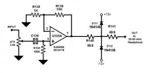
What did I do that was so offensive? Why would I try to make a fool out of you? I was just showing a circuit I was intending to use to replace the inverting one I was intending to use, just to keep the phase right.
The circuit below was the output on a preamp I designed and build in 2000, based on an AD project application for the SSM2017, also by Walt Jung.
And I really do not have the least idea what are those things you think I might be. Or why would I think I was.
Perhaps I shouldn't have mentioned anything about this preamp output.
Attachments
Last edited:
Perhaps you should also know what's before the filter, as there's a capacitor back there that should block all DC.
OTOS, maybe the correct way to do this is on the non-inverting version is to put the filter switch on the U102 feedback and select the low cut there.
Then I could replace R116 with 47K and use a 470n blocking cap before that. I guess that's the way you would prefer to set the input impedance.
OTOS, maybe the correct way to do this is on the non-inverting version is to put the filter switch on the U102 feedback and select the low cut there.
Then I could replace R116 with 47K and use a 470n blocking cap before that. I guess that's the way you would prefer to set the input impedance.
Attachments
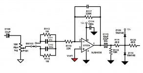
You could go down to 10k for R116 assuming C112 is adequately sized (things under 40 Hz presumably are not of primary concern in this application, so -3 dB at 20 Hz still seems adequate). C112 (and C111) must not be a ceramic though, it should be a film cap. At which point you may decide that a few µF worth of (bipolar) electrolytic aren't so bad after all...
With 10k/100k, output noise floor would be at about -92 dBV (down from -90 as shown). An equivalent non-inverting configuration (1k/9k1) gives -96 dBV. An improvement worth having IMO.
20 dB of gain seems a bit much for a 4556 and its 8 MHz GBW, but just try it first and see what you think.
With 10k/100k, output noise floor would be at about -92 dBV (down from -90 as shown). An equivalent non-inverting configuration (1k/9k1) gives -96 dBV. An improvement worth having IMO.
20 dB of gain seems a bit much for a 4556 and its 8 MHz GBW, but just try it first and see what you think.
I'm choosing those cap values to be able to use at least polyester types. At first I quoted polypropylenes, but they went away when re-evaluating cost.
This gain I did try it in the past and was also measured. Supply was a bit different though, as it was +/-9v. But these gain stage was approved by the THAT support when I showed it to them. And there even was another stage, which I eliminated that added 3dB more when balancing out.
What I'm not sure yet is what non-inverting layout to use, including the filter as part of it. It was easy on the inverting version, and it worked.
The parallel resistors were put in to eliminate switch thumps.
In the end, apparently we will go with split supplies after all for this project.
We should pick one of LT DC-DC based projects, that can output +/-12v, and feed with a small internal LiIon oe Lipo internal battery.
What I'm thinking now is using a simpler headphone amp, non-inverting, pot at the input in parallel with the preamp output.
Later I will see if it will need an output booster, using push-pull transistors.
One thing I'm not sure of is if putting an output capacitor or not. The chip I'm using has low offset, so I don't think I will need. But they always put an output cap on every commercial headphone amp.
Attachments
- Status
- Not open for further replies.
- Home
- Amplifiers
- Headphone Systems
- Portable headphone amp