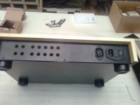
Gentlemen, I have just received a couple of images showing the case that Gerhard, my favourite carpenter, will send me by the end of this week.
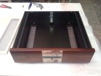
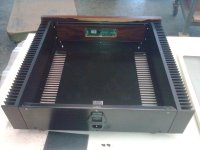
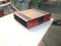
The three pictures on the left showing my "Integrated Amplifier's Case", the other 2 images showing the R-PRE Case!
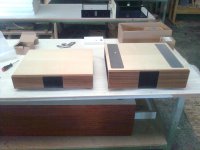
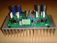
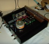
I am absolutely impressed by Gerhard's craftsman's skill and cannot wait to put my current NJW0 - SYMASYM (last picture) into his case.
Best regards - Rudi_Ratlos
The three pictures on the left showing my "Integrated Amplifier's Case", the other 2 images showing the R-PRE Case!
I am absolutely impressed by Gerhard's craftsman's skill and cannot wait to put my current NJW0 - SYMASYM (last picture) into his case.
Best regards - Rudi_Ratlos
Attachments
Gentlemen, I am the first one to receive the cases having ordered from Gerhard, my "favourite carpenter".
See my previous post!
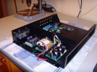
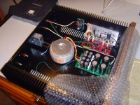
I have started with the Pre-Amplifier's case, housing my R-PRE, a modified version of CALVIN's line-buffer (layout of which has been done by myself) and Jean-Paul's DAC V2 - see 1st attached image.
You see a Schaffner Main's filter (with Power-On Switch and fuse-holder), followed by my "Soft-Power-On & DC-filter", a 30VA R-Core and the very nice PRE-PSU (being inspirated by Rephil!)
Gerhard's case is a lovely piece of workmanship, and I have never come across a case like this before.
This case cannot be compared with the soulless modushop cases!
I have asked Gerhard to provide me a separation plate (which I will paste up with some kind of µMetal) and an individual rear-plate. He did!
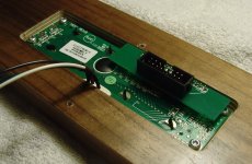
I have already finished his front plate (2nd image) and the PSU - section.
Gerhard's cases are "gems" (they are not "for nothing" though!), and I will go on very slowly and carefully with them.
Best regards - Rudi_Ratlos
See my previous post!
I have started with the Pre-Amplifier's case, housing my R-PRE, a modified version of CALVIN's line-buffer (layout of which has been done by myself) and Jean-Paul's DAC V2 - see 1st attached image.
You see a Schaffner Main's filter (with Power-On Switch and fuse-holder), followed by my "Soft-Power-On & DC-filter", a 30VA R-Core and the very nice PRE-PSU (being inspirated by Rephil!)
Gerhard's case is a lovely piece of workmanship, and I have never come across a case like this before.
This case cannot be compared with the soulless modushop cases!
I have asked Gerhard to provide me a separation plate (which I will paste up with some kind of µMetal) and an individual rear-plate. He did!
I have already finished his front plate (2nd image) and the PSU - section.
Gerhard's cases are "gems" (they are not "for nothing" though!), and I will go on very slowly and carefully with them.
Best regards - Rudi_Ratlos
Attachments
Last edited:
My next "little" project will be to replace the ALPS analog motorized potentiometer (used to control the LDR's LED-intensity) by a digital potentiometer (Potentiometer-PCB).
The digital potentiometer will be of course controlled by the R-PRE's µProcessor.
My DIY-friend METAL (with whom I have done a lot of successful projects in former days) got me to this idea.
Best regards - Rudi_Ratlos
The digital potentiometer will be of course controlled by the R-PRE's µProcessor.
My DIY-friend METAL (with whom I have done a lot of successful projects in former days) got me to this idea.
Best regards - Rudi_Ratlos
I like TO-3 transistors for a long time and I love the design you made of TO-3 SYMASYM here is a copy of a file you post for diy and what I did is just copied the best I can and I love it and thank you for share the file I don't remember in what post number lol , I love your work man also the new layout for this year 🙂
Best Regards
Juan
Best Regards
Juan
Attachments
Last edited:
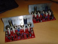
This is, how the TO3-SYMASYM actually looks like - in Gerhard's beautiful amplifier's case!
Regards - Rudi
Regards - Rudi
Attachments
Last edited:
But, Juan, this layout is long, long time ago!
I am happy to get rid of the "loops, the deadly power and GND - embraces"!
There are none on my current layout.
Best regards - Rudi
that is fantastic Rudi I didn't know about the GND loops ? any way thank you for sharing this new one this is awesome ! I appreciate it 🙂
Regards
Juan
Didn't you read AndrewT.'s replies concerning "power loops/embraces " in your DX - Super ClassA -amplifier thread?
Rudi
Rudi
Last edited:
I told you to go and read a Thread that specifically discusses LOW LOOP AREA............ I didn't know about the GND loops ? ....................
You replied that you would go and read.
Adopting better layout practice would cure the layout errors that you incorporate in all the layouts I can recall seeing in your posts.
ahaa! yes you did told me already stupid me, I apologize, I did read but not all is a lot to cover
Juan
Juan
You are not alone.
The vast majority of layouts whether for PSU or pre-amps or Power Amplifier ignore LOW LOOP AREA as something that needs due consideration.
One reason I do not use a PCB for PSU is that direct wiring gives a lower loop area.
The main reason is less cost.
But it's nice when less cost = better performance !
No wander I see a lot of vintage power amplifier that they do not use PCB for power supply, must of them use bridge rectifier to chassis and larger caps attached with heavy gauge wire and a GND STAR configuration "I mean example of course", I'm now reading the post, the twisted wire you mention I have seen that before on modern solid state audio amps is basicly same concept as the 6.3V heather wires that are twisted for tube amplifier that to avoid magnetic fields "example" I mean you know what I mean, ok I will continue reading the post, internal ground loop
Juan
Juan
Gentlemen, I have promised to Gerhard, who is my favourite carpenter and who has developped a series of very nice Audio-cases (as an example: image 1 shows his "small amplifier" - case)
to layout a new SYMASYM PCB that can be mounted directly on the heatsink - side-panels (see my post #861, which also shows the prototype of this new PCB) of his case.
In the meanwhile I have "optimized" the layout to include a speaker-protection circuit and a backend-PSU as well!
Don't call me crazy! I have layouted this big PCB in order to reduce the tooling-costs that the etching-company will ask from me!
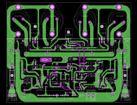
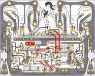
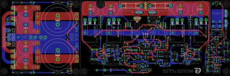
The new PCB (image 2) contains 3 sections:
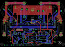
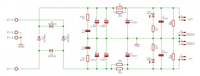
1) a backend-PSU (the schematic is given in image 3; if you want, I will cut it off the rest of the PCB)
2) the SYMASYM, which will use NJW0 - output transistors that (as well as the drivers and the BD139 TEMPCO transistor) need to be mounted beneath the PCB
3) the speaker-protection-circuit on the right side (you need not populate this section!)
The size of resulting PCB is 254 x 83mm.
I will give it the best quality available: 2mm FR4 PCB, 75µm copper, Gold immersion, black(!) soldermask and white silkscreen.
This big high-quality PCB will have its price though: 17€ (remember: the PCB contains 3 different sections!).
I will also offer the "hard to get" components to build this "Black Beauty":
- matched NJW0 output transistors, emitter resistors and input cap.
You can also decide if you want to have the PCB cut into 2 parts: PSU and SYMASYM/Speaker protection.
As usual I will prepare a "User's Manual", a BoM, a drill template, ...
This will be my last groupbuy for a SYMASYM.
You may either jump on the train or do not. It is up to you.
Tell me, in this thread, if you are interested in having the "SYMASYM Black Beauty".
Best regards - Rudi_Ratlos
to layout a new SYMASYM PCB that can be mounted directly on the heatsink - side-panels (see my post #861, which also shows the prototype of this new PCB) of his case.
In the meanwhile I have "optimized" the layout to include a speaker-protection circuit and a backend-PSU as well!
Don't call me crazy! I have layouted this big PCB in order to reduce the tooling-costs that the etching-company will ask from me!
The new PCB (image 2) contains 3 sections:
1) a backend-PSU (the schematic is given in image 3; if you want, I will cut it off the rest of the PCB)
2) the SYMASYM, which will use NJW0 - output transistors that (as well as the drivers and the BD139 TEMPCO transistor) need to be mounted beneath the PCB
3) the speaker-protection-circuit on the right side (you need not populate this section!)
The size of resulting PCB is 254 x 83mm.
I will give it the best quality available: 2mm FR4 PCB, 75µm copper, Gold immersion, black(!) soldermask and white silkscreen.
This big high-quality PCB will have its price though: 17€ (remember: the PCB contains 3 different sections!).
I will also offer the "hard to get" components to build this "Black Beauty":
- matched NJW0 output transistors, emitter resistors and input cap.
You can also decide if you want to have the PCB cut into 2 parts: PSU and SYMASYM/Speaker protection.
As usual I will prepare a "User's Manual", a BoM, a drill template, ...
This will be my last groupbuy for a SYMASYM.
You may either jump on the train or do not. It is up to you.
Tell me, in this thread, if you are interested in having the "SYMASYM Black Beauty".
Best regards - Rudi_Ratlos
Attachments

I'm interested in having a Stereo-Pair of the Black-Beauty with all off the hard-to-get components. But please list them for me with its price. (I'll decide, if i buy everything later; weitere Bemerkung: Bezahlung nur per Überweisung)
Best regards - willNamennichtnennen
Sorry for my bad english.
On my phone I cant see the pricelist as I should.
Best regards - willNamennichtnennen
Sorry for my bad english.
On my phone I cant see the pricelist as I should.
Last edited:
Hi Rudi,
I am quite interested in buying some PCBs. However, it would be very helpful to have a BOM upfront to estimate the costs for this projects.
Kind regards,
Michael
I am quite interested in buying some PCBs. However, it would be very helpful to have a BOM upfront to estimate the costs for this projects.
Kind regards,
Michael
- Home
- Group Buys
- TO-3 SYMASYM