Sagen.
It looks like you have built in BIG LOOPs inside the amplifier.
Where is the Flow and Return of the Left input signal?
Where is the Flow and Return of the Right input signal?
Where is the Return of the LEFT and the Return of the Right signal?
Is that a "ground buss" in the middle of the amplifier?
It has 4 separated connections. Each of those connections is at a different voltage !
You have two bridge rectifiers for a centre tapped transformer.
Where is the Zero Volts for each of the rectified supplies?
Where do the Zero Volts connect to the Chassis?
Last edited:
First you need to determine where the hum is being introduced.
Plug the power amp and preamp into the same power point with a double adapter.
If this does not fix it earth bust the preamp. Use a double adapter with the earth pin removed (DO NOT PLUG THE POWER AMP INTO THE EARTH BUSTED ADAPTER). This will earth the preamp through the power amp via the signal cable. Just be aware if you remove the signal cables your preamp is no longer earthed.
You could also try removing the signal earths and make sure the pre and power amps are plugged into the same power point.
A note of warning YOU ARE WORKING WITH MAINS VOLTAGE THAT IS DANGEROUS.
This is dangerous...................... earth bust the preamp. Use a double adapter with the earth pin removed (DO NOT PLUG THE POWER AMP INTO THE EARTH BUSTED ADAPTER). This will earth the preamp through the power amp via the signal cable. Just be aware if you remove the signal cables your preamp is no longer earthed.
You could also try removing the signal earths and make sure the pre and power amps are plugged into the same power point.
A note of warning YOU ARE WORKING WITH MAINS VOLTAGE THAT IS DANGEROUS.
One must never advise breaking the PE to Chassis connection.
This is dangerous.
One must never advise breaking the PE to Chassis connection.
Yes If you notice I add that in my post.
" Just be aware if you remove the signal cables your preamp is no longer earthed. "
The chassis is still grounded through the signal wires.
I work in the repair department of a Standards Electronics Calibration lab and we use this method often for measuring uV when our uncertainty needs to nano Volts.
AndrewT
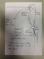
Flow and return of L/R signal goes inside the screened cable.
Its a groundrail ( from one piece copper ), but is not conected to chassi.
I will make a good stargrounding that is grounded to chassi and conects all 0V.
The cable from groundrail to RCA, is the only place today that has conection to chassi.
The bridge rectifiers, why I am no sure. I have had some help with the building, so cant answer on every detail. But is maybe some to do with the handling of Ampere (A)?
The zero volts for the rectifiers, dont have one I think.
wattjon
Thanx, but think I drop the test until I am getting more experience on my back ( :
Frank
I just had a thought (my mind is old) try rotating the transformer in the power amp 90° (I know it's a toroid) but this worked in a few amps I fixed for friends back in my early days as a hifi tech.
If you do not want to earth bust then you can remove the ground from the incoming RCA.
What happens is you have 2 paths to power earth. One is through the power amp power cable and the other is through the RCA returns then through the preamp power cable.
I suspect the problem is in your preamp. If breaking the RCA grounds fixes the problem, then open your preamp and check all of the ground connections for a high resistance.
Last edited:
AndrewT
Flow and return of L/R signal goes inside the screened cable.
Frank
Is the other black wire going from the RCA another ground. If so remove the ground inside the shield.
warrjon,
Do you mean rotate thetransformer 90' clockwise og conterclockwise seen from above?
Or standing on its side?
The preamp is grounded through powercable, the Power amp is not.
Do you mean cut of the cable from RCA to groundrail or the shield inside the signalcable. ( shield is just conected to signalreturn in RCA, not on the amp Board ).
Frank
warrjon,
Do you mean rotate thetransformer 90' clockwise og conterclockwise seen from above?
Or standing on its side?
Try rotating CW or CCW first. I have done this to my friends diy amp many years ago. Toroid TX's are different in their magnetic field so I do not know if it will work but its worth a try.
The preamp is grounded through powercable, the Power amp is not.
Does this mean your power amp has no power ground to the GPO.
Do you mean cut of the cable from RCA to groundrail or the shield inside the signalcable. ( shield is just conected to signalreturn in RCA, not on the amp Board ).
Can you draw a diagram of your wiring, as what you have described here does not match the last diagram you posted.

I just had a thought (my mind is old) try rotating the transformer in the power amp 90° (I know it's a toroid) but this worked in a few amps I fixed for friends back in my early days as a hifi tech.
I understand that Nelson Pass also does something like this.
warrjon
Ok, try that.
Poweramp have no ground through powercable ( only to cables inside ).
Remove the shield from the amp PCB, leave it connected at the RCA and leave the ground from the RCA to the ground bar.
What you have here is a ground loop with current able to flow through the RCA shield (BAD).
Last edited:
Hi warrjon
The shield is not connected at the amp PCB, only at the RCA.
If I cut where you point i will not have any return signal.
Shield stopps inside the cable 5mm before the amp PCB.
Frank
The shield is not connected at the amp PCB, only at the RCA.
If I cut where you point i will not have any return signal.
Shield stopps inside the cable 5mm before the amp PCB.
Frank
Hi warrjon
The shield is not connected at the amp PCB, only at the RCA.
If I cut where you point i will not have any return signal.
Shield stopps inside the cable 5mm before the amp PCB.
Frank
Sounds like you should try the reverse, isolate the RCA from the chassis, and ground the main star common. Then you'd have to ground the shield also.
Hi warrjon
The shield is not connected at the amp PCB, only at the RCA.
If I cut where you point i will not have any return signal.
Shield stopps inside the cable 5mm before the amp PCB.
Frank
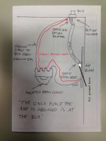
You do have a signal return path see diagram.
The way you have this wired you 2 return paths which current can flow, causing noise. Remove the return from the RCA at the PCB
Attachments
Sounds like you should try the reverse, isolate the RCA from the chassis, and ground the main star common. Then you'd have to ground the shield also.
The shield should be grounded at ONE end, not both. It then acts as a guard. If it is grounded at both ends current can flow in the shield (BAD) causing noise to be induced in the signal.
Be careful isolating the RCA from the chassis (It is a good idea) but make sure if you do the isolation is thick or the capacitance could cause problems. Best way is to cut a big section of chassis and mount RCA to a plastic block.
You will need to ground the block if the RCA is isolated
Last edited:
the connection from SOURCE to AMPLIFIER is a two wire connection.
This TWO wire connection must be continuous from Source to Amplifier, even through any intervening plugs/sockets and changes in wire type.
If a coaxial cable is used for part of the route from Source to Amplifier, then the screen of the Coaxial IS the RETURN part of the TWO wire connection.
The Screen MUST maintain the two wire route.
It MUST NOT BE BROKEN !
the connection from SOURCE to AMPLIFIER is a two wire connection.
This TWO wire connection must be continuous from Source to Amplifier, even through any intervening plugs/sockets and changes in wire type.
If a coaxial cable is used for part of the route from Source to Amplifier, then the screen of the Coaxial IS the RETURN part of the TWO wire connection.
The Screen MUST maintain the two wire route.
It MUST NOT BE BROKEN !
That is not quite right. I do this as my day job so have considerable experience with electrical noise caused by ground loops.
If the power amp and preamp are grounded at the power outlet this will also supply a return for signal, if you also have a return in the signal cable + other grounds, the difference in cable resistance will cause varying currents to flow around the grounds as soon as these currents become non-common mode you WILL get noise induced into the signal.
Last edited:
the Ground (Earth of Protective Earth (PE)) have NOTHING to do with Audio circuits.
The ONLY reason for adding in the PE is to stop us killing ourselves.
The signal connection whether it is the micro-volts from an FM aerial, or the mVac from a source, or the many volts from a power amplifier is ALWAYS a TWO WIRE connection.
You must know that.
The ONLY reason for adding in the PE is to stop us killing ourselves.
The signal connection whether it is the micro-volts from an FM aerial, or the mVac from a source, or the many volts from a power amplifier is ALWAYS a TWO WIRE connection.
You must know that.
- Home
- Amplifiers
- Power Supplies
- understanding star grounding