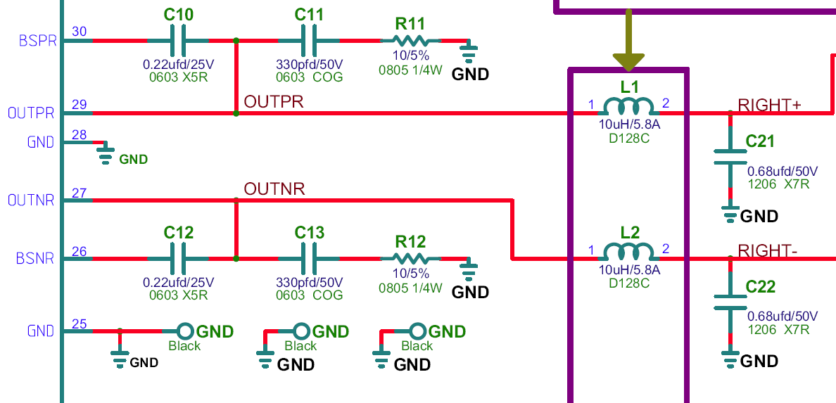
The topic of what bootstrap caps work or don't work on the TPA3116D2 seems to be the hot topic. I am not sure if this has been previously asked but I just realized that when I built my TPA3118D2 "Dead Bug Point-to-Point" amp, I followed the EVM circuit schematic. If you look at the EVM datasheet (http://www.ti.com/lit/ug/slou336b/slou336b.pdf), Fig. 2 shows a 330pF 50V COG ceramic cap connected in series with a 10ohm resistor to ground tied to the 220nF bootstrap cap:
Here is a closeup of the EVM snubber shown above:
Is this to "snub" the ringing that so many folks hear and complain about? When I listen to my dead bug amp, it sounds cleaner - less sibilance and I wonder if this is the case? Should we all be seriously trying this mod next? I think it might be a simple case of butt-soldered 330pF-10ohm connected to the 220pF bootstrap cap for SMT mods on Ybdz for example, and in the case of the YJ Blue/Black a simple 330pF axial and 10ohm 1/4-watt resistor can be added easily.
For comparison, the basic circuit that all of the Chinese boards out there use (except the one EVM copy) seems to be missing and may be a big part of the sound quality. The basic datasheet is here: http://www.ti.com/lit/ds/symlink/tpa3116d2.pdf Here is a closeup of the standard filter and bootstrap circuit:
What do you all think? Probably worth trying... certainly it is very inexpensive to add.
Yes this definitely needs pursuing!!!!!
Sharpi31,
That is a nice implementation with balanced input transformers too!
Can you describe the differences in sound quality with single ended caps vs the transformers?
That is a nice implementation with balanced input transformers too!
Can you describe the differences in sound quality with single ended caps vs the transformers?
I have four of these Bourns capable of 5 amps that I want to put in:
Invalid Request
http://www.bourns.com/data/global/pdfs/SRR1208.pdf
Some folks like the Coilcraft but they are huge and need creative mounting methods. The coils may be the next high value mod.
I also hear that using batteries is also very good as it kills all that SMPS noise (unless you are already using a fat linear supply with toroid and cap bank).
xrk,
There are other good quality Coilcraft inductors that have good spec and not that huge e.g. MSS1583. This model is almost identical in size to that on the stock board and is listed at $1.44 each.
Regards,
I should explain my limited experience with input caps & transformers, so you understand the context of my preferences. I've tried the generic input caps on both the Sure TPA3110 and Audiobah TPA3116 boards. In both cases the amps were nice enough to listen to but sounded a bit edgy and lacking in depth compared to my other good amps. Upgrading the + side input cap to a larger value standard MKP cap on the TPA3110 board got rid of some of the edginess, but I didn't change the - side cap to ground so can't comment on the effect this would have. My instincts tell me that using the same type and value of cap should on both + & - inputs (even though the - input is connected to ground) should be best, but I haven't confirmed this.
After realising the potential to swap coupling caps for a transformer, I didn't play with caps any more. Aside from losing the coupling caps, the transformer would provide galvanic isolation for the source and act as a low pass filter between source and amp, minimising noise transmission between source and amp. Additionally, the transformer would allow for both the + & - inputs on the amp to be driven equally, even if an unbalanced source was used. Another bit of unsubstantiated instinct on my part, but I feel that an amp with differential inputs should ideally be driven with a differential signal (rather than one input being tied to ground when an unbalanced source is used),
Both the Amethyst and Lundahl transformers tested were obviously better than the caps I'd tried (smoother but more detailed, far better image depth). The Lundahls have a more open high end but bass remains full and defined. The Amethyst ones were more mid-focused but still richer than the caps.
I'm sure caps can provide better results than I achieved (decent larger value caps on both + & - inputs) so would encourage you to try both, if possible, and share your findings,
Lo Tse,
Thanks for the tip on the inductors from Coilcraft. I will order some - those have some pretty high saturation currents.
My next mods will be in this order:
1. Bootstrap snubber with 330pF ceramic and 10ohm resistor.
2. Coilcraft inductor you recommended
3. Avcc power supply decoupling and bypass cap
4. Battery power supply
5. Balanced Input transformers
Last edited:
What do you all think? Probably worth trying... certainly it is very inexpensive to add.
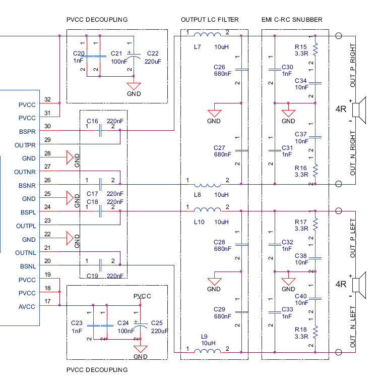
NXP's classD chip suggested applications have similar snubbers which have evolved slightly over time. They now use 220pF from both rails to create a capacitive potential divider and the 10R is fed from this mid-rail bias point.
Attachments
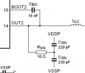
I don't understand how the Nxp snubber works? It snubs the ringing to the rails rather than to ground? On the TI snubber, the cap comes before the resistor. With Nxp the resistor comes before the cap and the potential dividers would need a positive and negative rail right?
Do you think it is ok to have the snubber farther away from chip pin? Easier to implement on Ybdz amp this way as there are exposed traces leading to inductors that are farther from chip. I don't want to remove the heat sink.
Do you think it is ok to have the snubber farther away from chip pin? Easier to implement on Ybdz amp this way as there are exposed traces leading to inductors that are farther from chip. I don't want to remove the heat sink.
xrk,
There are other good quality Coilcraft inductors that have good spec and not that huge e.g. MSS1583. This model is almost identical in size to that on the stock board and is listed at $1.44 each.
Regards,
Hi,
Couldn't find this model in Mouser, do you have the Mouser part number?
Thanks
I don't understand how the Nxp snubber works? It snubs the ringing to the rails rather than to ground?
Yes, given that the output stage has no ground connection, it means the current travels in smaller loops. Returning snubber current to ground means it'll have to pass through a decoupling capacitor somewhere to complete the loop.They adopt this technique on both sysmmetric and asymmetric supplies. It would also make sense to adopt this style for output zobel networks where they're BTL, but that would mean more caps. I guess when the caps are just 0603 size or smaller that's not too much of a worry.
On the TI snubber, the cap comes before the resistor. With Nxp the resistor comes before the cap and the potential dividers would need a positive and negative rail right?
In series-connected components the order's not important in general. Yes the junction of the two caps would typically be at PVCC/2 but at a very high impedance at DC. The AC impedance is what matters though for snubbing.
Do you think it is ok to have the snubber farther away from chip pin? Easier to implement on Ybdz amp this way as there are exposed traces leading to inductors that are farther from chip. I don't want to remove the heat sink.
The closer the better for reliability. The snubber reduces momentary over-voltage from the ringing on fast edges - every nH of extra inductance increases the stress on the IC. I seem to recall 5mm distance being the recommended maximum but I don't know how this figure is arrived at.
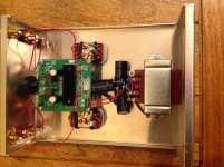
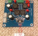
My Audiobah board implementation - no hum from speakers, just slight hiss with my ear to the driver (as good as I've had from any amp). Thanks for all the useful info from others.
It looks like you have a cap and resistor across the transformer secondaries. Are these for impedance matching? What values did you use, and how did you arrive at them? Also, are the grounds connected underneath the board?
Most 3116 amps do have the post-filter snubber. The SMSL has prefilter. The pre-filter snubber probably does the same only befor filter can get excited and peak🙂 I think it could be anywhere, bootstrap was convenient. The pre-filter snubber isn't optional on the EVM, post-filter is optional I believe? Prefilter can take away some work from inductors.
It looks like you have a cap and resistor across the transformer secondaries. Are these for impedance matching? What values did you use, and how did you arrive at them? Also, are the grounds connected underneath the board?
The RC filter on the secondaries of the LL1540 is 22Kohm + 1nF (straight datasheet implementation for loads >25KHz: http://www.lundahl.se/pdf/1540.pdf
One slightly odd thing about the Audiobah board is that the ground plane on the bottom of the PCB extends to each mounting hole. I used brass PCB pillars so the amp board ground is connected to the chassis at four points. Incoming mains earth is tied directly to the chassis via one of the power transformer fixings. I haven't added any wires linking mains earth to PSU ground, but there doesn't seem to be any problem with this connection coming via the aluminium chassis and brass PCB pillars (I know this isn't best practice though). My approach was to wire things up this way and then review the scheme, if hum etc. we're an issue. The incoming signal and ground are only connected to the Lundahl transformer primary, so isolated from the amp. The Lundahl datasheet suggests that the centre tap of the secondaries should be tied to ground, but I've left this floating given the 3V bias of the amp signal inputs.
I have an YBDZ blue board and volume is too low. Is there an easy way to change input gain to 36db? Should I change my volume pot? Now I am using a 100k pot.
I think it could be anywhere, bootstrap was convenient. The pre-filter snubber isn't optional on the EVM, post-filter is optional I believe? Prefilter can take away some work from inductors.
I just ordered the 330pF C0G 200V ceramics and 10ohm thin films (thru hole components). I will start by mounting where convenient and the Ybdz board has a big fat exposed trace leading from the IC to the SMT coil. I am thinking of soldering straight onto those in a short pedestal and then the resistors all tied to each other in a ground bus bar that is anchored to the board like a horizontal catwalk across the four main traces. Alternatively, I could scrape off the shellac covering the ground plane near each trace and use all SMT components (which I have already when I built my first 3118 dead bug).
Last edited:
I have an YBDZ blue board and volume is too low. Is there an easy way to change input gain to 36db? Should I change my volume pot? Now I am using a 100k pot.
It is easy if you are familiar with removing and soldering SMT components. There are two resistors on the front middle of the board (under the heatsink which needs to be removed to do this) - see photo below. Read the datasheet and it will list the resistor values needed. Note that this will drop your input impedance to only 9kohm - this means that your source needs to be able to drive a 9kohm load. The pot has no effect on how loud it can go as it only serves to reduce the input signal via voltage divider.
My "blue" Ybdz actually has 26dB gain and not 32dB as used in earlier versions. I think the values of the resistors needed for 36 dB are 47 kΩ and 75 kΩ. Look at videos on Youtube on how to solder SMT components and practice on an old scrap piece of PCB like a defunct PC graphics card that you would throw away. You will need headband goggle magnifiers, good metal tweezers, a fine point soldering iron, steady hands, and patience. It can be a lot of fun though to work on miniature soldering.
Attachments
Last edited:
The RC filter on the secondaries of the LL1540 is 22Kohm + 1nF (straight datasheet implementation for loads >25KHz: http://www.lundahl.se/pdf/1540.pdf
One slightly odd thing about the Audiobah board is that the ground plane on the bottom of the PCB extends to each mounting hole. I used brass PCB pillars so the amp board ground is connected to the chassis at four points. Incoming mains earth is tied directly to the chassis via one of the power transformer fixings. I haven't added any wires linking mains earth to PSU ground, but there doesn't seem to be any problem with this connection coming via the aluminium chassis and brass PCB pillars (I know this isn't best practice though). My approach was to wire things up this way and then review the scheme, if hum etc. we're an issue. The incoming signal and ground are only connected to the Lundahl transformer primary, so isolated from the amp. The Lundahl datasheet suggests that the centre tap of the secondaries should be tied to ground, but I've left this floating given the 3V bias of the amp signal inputs.
Thanks sharpi31. This helps tremendously. I can't wait to implement this myself.
It is easy if you are familiar with removing and soldering SMT components. There are two resistors on the front middle of the board (under the heatsink which needs to be removed to do this) - see photo below. Read the datasheet and it will list the resistor values needed. Note that this will drop your input impedance to only 9kohm - this means that your source needs to be able to drive a 9kohm load. The pot has no effect on how loud it can go as it only serves to reduce the input signal via voltage divider.
My "blue" Ybdz actually has 26dB gain and not 32dB as used in earlier versions. I think the values of the resistors needed for 36 dB are 47 kΩ and 75 kΩ. Look at videos on Youtube on how to solder SMT components and practice on an old scrap piece of PCB like a defunct PC graphics card that you would throw away. You will need headband goggle magnifiers, good metal tweezers, a fine point soldering iron, steady hands, and patience. It can be a lot of fun though to work on miniature soldering.
Seems to be a lot of work and I don't have much free time right now, so I will settle down to what it is. Anyway, thanks for your answer xrk971!
Just a reminder for those that forgot. (and for those that don't know)
🙂
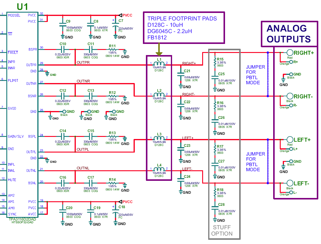
GB PBTL TPA3116/8 not just bare pcb
Final features here:
http://www.diyaudio.com/forums/group-buys/257996-gb-tpa3116-8-pbtl-bare-pcb-8.html
post 79
🙂
Doug
🙂
GB PBTL TPA3116/8 not just bare pcb
Final features here:
http://www.diyaudio.com/forums/group-buys/257996-gb-tpa3116-8-pbtl-bare-pcb-8.html
post 79
🙂
Doug
I have an YBDZ blue board and volume is too low. Is there an easy way to change input gain to 36db? Should I change my volume pot? Now I am using a 100k pot.
Just a reminder for those that forgot. (and for those that don't know)
🙂
GB PBTL TPA3116/8 not just bare pcb
Final features here:
http://www.diyaudio.com/forums/group-buys/257996-gb-tpa3116-8-pbtl-bare-pcb-8.html
post 79
🙂
Doug
Wow, that is a lot of features. 😀
Does this refer to the pre-LC filter snubber connected to the bootstrap caps that I am discussing in the previous posts?I have added the snubber directly on the outputs as in the ap note. The R is 1206 and the C is 0805.
- Home
- Amplifiers
- Class D
- TPA3116D2 Amp