Hi and i am perfectly willing to agree with you. It was mainly the friend that is obsessed with these things.
I just like good parts but not exotic ones.
Good to know that active parts are the most critical.
I think that the simulations have answered most of my questions.
That is that acting of the various conditions like Vsupply, bias currents and so on very low distortion figures can be obtained with quite basic topologies.
I have to simulate something for myself now.
Thanks again for the helpful advice.
Kind regards, gino
There is a lot of optimization done during simulation, and now with that wonderful tool you can try many configuration and do fine adjustments, and then build and try better components, but don't overdo with exotics.
There is a lot of optimization done during simulation, and now with that wonderful tool you can try many configuration and do fine adjustments, and then build and try better components, but don't overdo with exotics.
Thank you very much again for your kind and valuable advice
Actually the plan is just that, to try to play a little with this sim SW to see how different working conditions impact the performance
And of course i will start very basic.
My idea is that i will find a very very very basic topology with decent performance i will try to build it
It will be my first line stage 😀
And i swear ... no exotic parts at all. Just good part from RS or similar.
Thanks a lot again.
Kind regards, gino
Hi,
if to choose a Diamond Buffer I´d opt for the cross-coupled version as linked in #10 and shown in #18.
The additional source resistors for the drivers allow for easy control and sufficient amount of the output transistors bias current.
As in #1 and #3 the drivers run hotter than the output trans, which are too low in Bias.
Also the cross coupling keeps the (mean) Vce of the drivers positive and reduces the heat power losses of the drivers considerably against the #3 version (where the sources are connected to the supply rails).
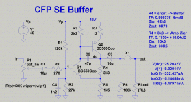
The circuit in +26 is an amplifier with a gain of ~+10dB.
It´d become a Buffer if R33=3k3 were shorted.
It´d also introduces some tweaks.
1) Transistor pair BC550C/BC60C
2) Supply between 24 and 48V. Lower than 24V and distortion rises, higher than 48V and heat power losses get high. THD is low enough in any case and besides it depends more on signal level and load impedance.
3) add a input LP-filter of 270R/1.2nF to prevent HF from entering the circuit. Also the CFP tends to oscillate ... bandwidth limiting (400kHz) might help.
4) add a emitter resistor of 12R-15R to the output transistor.
5) change the output resistor from 47k to 100k. Its just there to leak away the electrolytics charge.
If configured as amplifier the load impedance should be >>1k for inputs >=1Vrms.
Output transistor runs into current clipping, due to Bias current of +5mA.
jauu
Calvin
Attachments
Hi,
if to choose a Diamond Buffer I´d opt for the cross-coupled version as linked in #10 and shown in #18.
The additional source resistors for the drivers allow for easy control and sufficient amount of the output transistors bias current.
As in #1 and #3 the drivers run hotter than the output trans, which are too low in Bias.
Also the cross coupling keeps the (mean) Vce of the drivers positive and reduces the heat power losses of the drivers considerably against the #3 version (where the sources are connected to the supply rails).
The circuit in +26 is an amplifier with a gain of ~+10dB.
It´d become a Buffer if R33=3k3 were shorted.
It´d also introduces some tweaks.
1) Transistor pair BC550C/BC60C
2) Supply between 24 and 48V. Lower than 24V and distortion rises, higher than 48V and heat power losses get high. THD is low enough in any case and besides it depends more on signal level and load impedance.
3) add a input LP-filter of 270R/1.2nF to prevent HF from entering the circuit. Also the CFP tends to oscillate ... bandwidth limiting (400kHz) might help.
4) add a emitter resistor of 12R-15R to the output transistor.
5) change the output resistor from 47k to 100k. Its just there to leak away the electrolytics charge.
If configured as amplifier the load impedance should be >>1k for inputs >=1Vrms.
Output transistor runs into current clipping, due to Bias current of +5mA.
jauu
Calvin
BC550/560 are very good because of their low-noise nature and high hfe (around 550), however Gino requested 60V supply - in this case they are close to the edge (if not out) of SOA. Also, 5 mA at almost 40V (200mW) is too much power for BC560.
I totally agree, 48V supply is somewhat optimal for this circuit and emitter resistor for Q2 will increase stability. Just make sure to take care of Q2's heat dissipation anyway 😉
Hi,
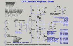
Going complementary again and combining the cross-coupled Diamond and the CFP, allowing to jumper for either Gain-mode or Buffer-mode might look like this.
(fully SMD, low-voltage Dual Supply, 600R balanced capable)
jauu
Calvin
Why not waste some Volts and watts and regulate the 60V down to ~48V? 😉Gino requested 60V supply
Going complementary again and combining the cross-coupled Diamond and the CFP, allowing to jumper for either Gain-mode or Buffer-mode might look like this.
(fully SMD, low-voltage Dual Supply, 600R balanced capable)
jauu
Calvin
Attachments
Last edited:
Calvin,
you very kindly gave a lot of supplementary data to the asc of post43.
I see the Rin=15k3
The 27k//120k gives ~22k.
There is a missing 50k to give the final value of 15k3.
Is the input impedance of the BJT (Q1) ~50k?
you very kindly gave a lot of supplementary data to the asc of post43.
I see the Rin=15k3
The 27k//120k gives ~22k.
There is a missing 50k to give the final value of 15k3.
Is the input impedance of the BJT (Q1) ~50k?
Last edited:
.......................
Is the input impedance of the BJT (Q1) ~50k?
Have you calculated it for me?most likely,..............the input resistance of Q1.....
Can you show how to calculate the BJT input impedance?
Hi,
Why not waste some Volts and watts and regulate the 60V down to ~48V? 😉
Going complementary again and combining the cross-coupled Diamond and the CFP, allowing to jumper for either Gain-mode or Buffer-mode might look like this.
(fully SMD, low-voltage Dual Supply, 600R balanced capable)
jauu
Calvin
I used different cascoded Diamond buffer for GainWire mk2 line/phone amp, with very low distortion when used with no GNFB and vanishing low when used as CFA. . http://www.diyaudio.com/forums/solid-state/235695-no-nfb-line-amp-gainwire-mk2-25.html#post3799212 and I plan to make it next in SMD.
Damir
Hi!!
I build this simple Buffer 2 Years ago and it works fantastic very neutral Sounding.
Greatings From Croatia!!!
An externally hosted image should be here but it was not working when we last tested it.
That`s very good implementation, Input bjt`s are cascoded and there`s no need for extra cascode, maybe ccs for a input bjt emitter load.😉
Have you calculated it for me?
Can you show how to calculate the BJT input impedance?
afaik, input impedance is beta times re, but
i do not want to repeat what others have done,
that is what simulators are for,
i would rather build it and then have a listen,
after all that was what the discussion and simulation was all about,
hey this is DIY and people build things, is it not?
i do not value precision for precision's sake, there are
practical side to all these....
i have seen this topology in the TI manuals from the early 80's,
nothing new here except the use of simulators....
topologies come and go....happens all the time...
nice one Basi, if memory serves me right, i have seen this topology in one of Marantz amps, couldn't recall the model number as only the guts and power traffo was given to me to repurpose....
Thanks Elvee for your suggestion.
I put it even father and now distortion at 20kHz is 0.000002%.
I am going to use one of those buffers in my lineamp(no NFB) and I am not sure if the complexity is to much as the gain block is in 1ppm region.
Could be that simpler version of the buffer is good enough.
Damir
Hi, very impressive measurements.
I am a beginner with Spice sims and this circuit is unbelievable ...
Sorry i got lost a little in the replies 😱, but i wonder if your have actually built it.
If i understand well the sim results fix the theoretical max we can obtained from a circuit.
Anyway congratulations again for this result. Impressive.
Never seen something of similar.
Thanks and regards, gino
Gino, very similar buffer was used in my GainWire mk2 line&phone preamp, 20 PCB sold.
Damir
Gino, very similar buffer was used in my GainWire mk2 line&phone preamp, 20 PCB sold.
Damir
Hi Damir, i have found the 3d about the amp but not the one about the preamp. I am mostly interested in buffers. No voltage gain needed.
Where i have to look for the pcb ?
Thanks and regards, gino
Hi Damir, i have found the 3d about the amp but not the one about the preamp. I am mostly interested in buffers. No voltage gain needed.
Where i have to look for the pcb ?
Thanks and regards, gino
Gino,goto post #20, there you will find the link, Danir.
Gino,goto post #20, there you will find the link, Danir.
Thanks a lot Damir.
Kind regards, gino
- Status
- Not open for further replies.
- Home
- Amplifiers
- Solid State
- Simple line buffer


