
Mooly please help set dc offset
Dear Mooly!
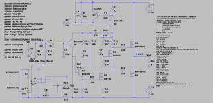
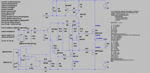
I decided to build this amp but I cannot set oVDC at the output, with right schematic I got +1.5V at Vout, which component should be changed?
attached sch and asc file,
thank you in advance for your answer😀
Dear Mooly!
I decided to build this amp but I cannot set oVDC at the output, with right schematic I got +1.5V at Vout, which component should be changed?
attached sch and asc file,
thank you in advance for your answer😀
Attachments
Dear Mooly!
I decided to build this amp but I cannot set oVDC at the output, with right schematic I got +1.5V at Vout, which component should be changed?
attached sch and asc file,
thank you in advance for your answer😀
Interesting to see a sim of it. You need to drop the value of R6 to 2k in the sim. The TL071 model draws more current than a real device and its pulling the zener regulated supply down.
Edit... also make C7 a 1uf for the sim transient to run.
Interesting to see a sim of it. You need to drop the value of R6 to 2k in the sim. The TL071 model draws more current than a real device and its pulling the zener regulated supply down.
Edit... also make C7 a 1uf for the sim transient to run.
thank you very much, now it works🙂
attached files for interested
bye

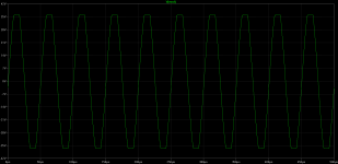
N-Period=1
Fourier components of V(vout)
DC component:-0.00467607
Harmonic Frequency Fourier Normalized Phase Normalized
Number [Hz] Component Component [degree] Phase [deg]
1 2.000e+04 5.207e+00 1.000e+00 -4.75° 0.00°
2 4.000e+04 4.686e-03 9.000e-04 99.27° 104.02°
3 6.000e+04 1.380e-03 2.650e-04 8.03° 12.78°
4 8.000e+04 2.144e-04 4.118e-05 -82.93° -78.18°
5 1.000e+05 4.898e-05 9.408e-06 -172.27° -167.52°
6 1.200e+05 1.079e-05 2.073e-06 97.52° 102.27°
7 1.400e+05 2.603e-06 5.000e-07 7.72° 12.47°
8 1.600e+05 6.333e-07 1.216e-07 -81.24° -76.49°
9 1.800e+05 1.434e-07 2.754e-08 -175.10° -170.35°
Total Harmonic Distortion: 0.093919%
Attachments
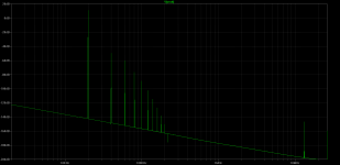
Thanks for posting the sim and pictures 🙂 Just under 0.1% isn't to bad at all on the face of it.
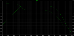
I've got another version that can be switched between global feedback and non global. I'll post the sim in a minute for anyone interested.
I've got another version that can be switched between global feedback and non global. I'll post the sim in a minute for anyone interested.
I've got another version that can be switched between global feedback and non global. I'll post the sim in a minute for anyone interested.
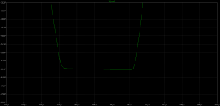
of course, please send!
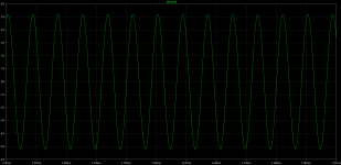
in meantime clipping show:
Attachments
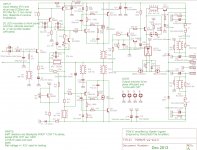
Here you go. The files are "as is" with the servo over ridden by the DC offset programmed into the input voltage source and the feedback return cap replaced with a voltage source.
I'm not sure what state all the other files were left in but they should be essentially ready to roll 😀
Open circuiting the resistor marked "FB Set" will make it run without global feedback.
I'm not sure what state all the other files were left in but they should be essentially ready to roll 😀
Open circuiting the resistor marked "FB Set" will make it run without global feedback.
Attachments
-
Cordell Models.txt19.6 KB · Views: 110
-
FV V2_0 DC Operating Conditions.asc13.5 KB · Views: 102
-
FV V2_0 Damping Factor And Output Impedance.asc13.4 KB · Views: 106
-
FV V2_0 CCIF Intermodulation Distortion.asc13.7 KB · Views: 119
-
FV V2_0 40Khz Squarewave.asc14.2 KB · Views: 155
-
FV V2_0 20Khz THD.asc13.7 KB · Views: 133
-
FV V2_0 1Khz THD.asc13.8 KB · Views: 116
Hmm....the Mooly Amp, but on steroids, lots of LATFET steroids.
Thanks, its something like that 😀 I have an AC coupled version too, which includes an experiment into "current drive" (where the output voltage depends on varying load impedance).
I have an AC coupled version too, which includes an experiment into "current drive" (where the output voltage depends on varying load impedance).
very interesting, please show🙂
my favourite design however is from the 1st post😉
very interesting, please show🙂
my favourite design however is from the 1st post😉
😉
This one includes a SS output relay and rapid forced charge of the coupling cap to ensure totally silent switch on/off.
Attachments
Mooly, did you experience too that current drive of loudspeakers sounds better than voltage?
Now I am driving my speakers (96dB eff.) from vfa through 100 ohm resistors in series with excellent sonic quality😎
Now I am driving my speakers (96dB eff.) from vfa through 100 ohm resistors in series with excellent sonic quality😎
At the moment the whole idea is just a concept and not a real build. I must try the resistor method to get some idea of how it sounds... interesting to hear that you like the results.
Member
Joined 2009
Paid Member
😉
This one includes a SS output relay and rapid forced charge of the coupling cap to ensure totally silent switch on/off.
This is getting closer to my TGM8 amplifier. Both have singleton input and buffered VAS (although I used the buffer to bootstrap the singleton for higher input gain). Both have a VFET to provide 'low angle assist' and both have solid state relay on the output. However, instead of LatFET I used BJT output and I used CFP output - you don't have CFP but still your topology is close to CFP. I can tell you the sound is very good 🙂
You could almost take the TGM8 and use a LatFET in place of the BJT output and you'd be almost there.
Attachments
Last edited:
Thanks for sharing 🙂
I became a convert to the singleton input and latfet outout with my now somewhat ancient original design, but as you say, they sound wonderful.
The idea for the hybrid type output (latfet and vertical fet) came from this,
http://www.diyaudio.com/forums/soli...nd-lateral-fet-higher-power-class-ab-amp.html
And although I didn't use LTSpice at the time I've since been able to simulate it.
Attachments
Member
Joined 2009
Paid Member
I do like the hybrid outputs, I have seen them dotted around the internet but they haven't been as popular as I would expect. I liked the idea to keep the 'sound' from a single output pair and of course this means no need for matching - the extra FETs only assist when needed so they operate in Class C (where they are thermally stable).
I've never used LatFETs though - not sure of a reliable supply at good prices ?
I've never used LatFETs though - not sure of a reliable supply at good prices ?
This is quite different to mainstream thinking - and design obviously - to anything I've seen here. I won't ask what you've been eating for breakfast lately but I'm interested in the why and how you arrived at the section "speaker" including the pulsed charging voltage.😉.....This one includes a SS output relay and rapid forced charge of the coupling cap to ensure totally silent switch on/off.
The VAS is also "something else". Is U1 developing a protection/disabling voltage for it? Would you care to walk us through it some time? 😕🙂
This is quite different to mainstream thinking - and design obviously - to anything I've seen here. I won't ask what you've been eating for breakfast lately but I'm interested in the why and how you arrived at the section "speaker" including the pulsed charging voltage.
The VAS is also "something else". Is U1 developing a protection/disabling voltage for it? Would you care to walk us through it some time? 😕🙂
Thanks for the interest Ian... remember its just a concept/ideas at the moment rather than a fully worked design.
The quick charge for the speaker coupling cap is just a way to use a single FET to connect a 10 ohm (R28) to ground for a predetermined period at switch on to rapidly charge the cap. During this time the SS speaker relay is off (open). When the speaker relay closes the "charge FET" would be turned off. The diode bridge allows use of a single polarity FET to achieve the switching. A single FET on its own wouldn't be suitable due to the "built in" diode across D-S.
The opamp is just an experimental idea, nothing more at this stage, and works by modulating the VAS stage allowing some approximation to current drive. As the load impedance rises, the amplifiers output voltage rise too.
- Status
- Not open for further replies.
- Home
- Amplifiers
- Solid State
- New Design-HEXFET Poweramp. Sonic benefits of this approach.