Congratulation to all of you. May-you enjoy each and every second of this happiness.
Jayden don't know-it yet, but she has an exceptional grand father 🙂
Jayden don't know-it yet, but she has an exceptional grand father 🙂
Waly -- You are Something ----
The bias vs thd doesnt seem to be symmetrical. A lower than optimum (min thd) will raise the thd very quickly. But if biased above the optimum level the THD only increases gradually. So higher than optimum would be preffered. But for another reason as well...... the thermal affects on many idle bias circuits are not optimized either --- they cause the idle to move down to below the optimum after the signal has been high and then shift to low level (or even to zero as between tunes). This temp bias shift to lower level causes the distortion to increase dramatically during this period -- while temp/bias is stablizing to its' preset value.
Can you detail some design means and methods of biasing to eliminate the thermal bias shifts..... as the OPS heats and cools. It should not happen in well designed circuits but it is very common occurance. Perhaps because of the practice of measuring at stablized, constant power/temp levels this gets over-looked as a real source of distortion.
It could use more attention in Bob or Self's book also.
Note- because the sound quality is best and the measured thd is lowest when Rb and Re is lowest... I will always match OPS devices to minimize current hogging caused by the use of the low values.
THx-RNMarsh
Last edited:
"In April I became a grandfather for the first time. What a pleasure!"
Congratulations Bob - that's certainly a milestone worth hitting!
Congratulations Bob - that's certainly a milestone worth hitting!
Richard, I agree that the lower Re's can confer lower distortion, but you really have to have fast, carefully designed thermal comp to get this to be reliable. This does not mean I endorse higher Re to get away with sloppy engineering, but higher does give more stability. I tend to bias my output stages rich in any event ( I prefer the sound to lower bias levels).
I have taken a different tack in my e-Amp where I use what I term 2 point thermal comp. What I do is design the comp so that it intersects the correct bias current at a low temp and at a high temp. The bias curve is then flat and for the most part tracks temp accurately. A refinement of this technique would be 3 point compensation for an even flatter, more accurate response. Once characterized for a particular mechanical configuration, you only need one adjustment at ambient.
(On the Rb issue, I will try 3.3 or 2.2 in my next design. It's that 500 AFEC watter I mentioned a few hundred posts back. I am still mulling the thermal constraints. I have bought a 5U x 500 mm deep case from Modushop. Will have to wait until my wife is not looking before I order the transformers 😀 )
Last edited:
I believe you are all talking about BJT Re and base stopper influence. What about Laterals FET or BIGBT ?
I believe you are all talking about BJT Re and base stopper influence. What about Laterals FET or BIGBT ?
.... and mind reader, too ?? 🙂
Maybe we can get insights in this aspect from Bob C. and his FET OPS designs. I have used some of them specifically for their neg thermal coeff and other benefits but lets hear from The Man as he is a strong proponent.
OOOooooH, BOB !! Can you come over here for a minute ??
THx-RNMarsh
Richard, I agree that the lower Re's can confer lower distortion, but you really have to have fast, carefully designed thermal comp to get this to be reliable. This does not mean I endorse higher Re to get away with sloppy engineering, but higher does give more stability. I tend to bias my output stages rich in any event ( I prefer the sound to lower bias levels).
I have taken a different tack in my e-Amp where I use what I term 2 point thermal comp. What I do is design the comp so that it intersects the correct bias current at a low temp and at a high temp. The bias curve is then flat and for the most part tracks temp accurately. A refinement of this technique would be 3 point compensation for an even flatter, more accurate response. Once characterized for a particular mechanical configuration, you only need one adjustment at ambient.
(On the Rb issue, I will try 3.3 or 2.2 in my next design. It's that 500 AFEC watter I mentioned a few hundred posts back. I am still mulling the thermal constraints. I have bought a 5U x 500 mm deep case from Modushop. Will have to wait until my wife is not looking before I order the transformers 😀 )
I know--- lower values just makes things even harder....but the sound is really improved so I have no choice.
Your method of temp comp..... can it be applied to any DIY amp... as a mod or replacement? Sounds like an excellent result which will be especially needed to keep the THD in its narrow(er) null point. Should sound great all the time, then. I'll take a closer look now.
THx - Richard
Managed BIAS?
Hi All,
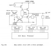
What do you think about the "managed" approach to BIAS regulation?
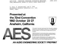
I attach a principal diagram and a title page of the paper where it was published (1986).
Looks like a good approach to me. Thinking about prototyping. Of course, it will be based on a modern controller, having ADCs/DACs embeded. One chip can handle 2 channels independently.
Main advantage - we control the BIAS not only based on temperature, but also on the output signal level, minimizing effects, like temporary BIAS drop below optimum after high signal disappears.
It will require some research and experiments, but looks attractive.
Does it make sense to you?
Cheers,
Valery
Hi All,
What do you think about the "managed" approach to BIAS regulation?
I attach a principal diagram and a title page of the paper where it was published (1986).
Looks like a good approach to me. Thinking about prototyping. Of course, it will be based on a modern controller, having ADCs/DACs embeded. One chip can handle 2 channels independently.
Main advantage - we control the BIAS not only based on temperature, but also on the output signal level, minimizing effects, like temporary BIAS drop below optimum after high signal disappears.
It will require some research and experiments, but looks attractive.
Does it make sense to you?
Cheers,
Valery
Attachments
Richard, you take a standard CFP Vbe spreader and you across the base of the NPN sense transistor and the emitter of the pass transistor (I.e top of the the spreader) you add a 10 k NTC in series with a resistor.
To cal: replace the resistor in series with the NTC with a 20 k pot set to 10 k
At ambient, adjust the Vbe spreader for the correct OPS bias.
Now drive the amplifier until the heatsink temperature reaches 60 degrees C
Adjust the 20k pot so that at 60 deg C, you again get the correct OPS bias.
Lets the amp cool, and then remove the pot and measure the value. Replace the pot with a fixed resistor. This completes calibration and the resistor value is fixed for that mechanical configuration.
When you adjust the pot at high temp, this has the effect of pushing the original ambient cal point down so the correct bias current intercept point lies 10 to 15 degrees lower. For this reason, I like to do the first cal point at about 30 or 35 C.
What you have now is a system that by design intersects the ideal bias current in 2 places. It's quite flat and the deviation from ideal is small. If you have a fast response thermal comp loop, you can get quite accurate results. As I mentioned earlier, adding a third cal point would give even better tracking and lower errors.
I have had this running for about 18 months on the e-Amp and it's very stable with no issues, so I feel it's a simple robust technique and will use it on my mx-Amp.
Last edited:
Hi All,
What do you think about the "managed" approach to BIAS regulation?
I attach a principal diagram and a title page of the paper where it was published (1986).
Looks like a good approach to me. Thinking about prototyping. Of course, it will be based on a modern controller, having ADCs/DACs embeded. One chip can handle 2 channels independently.
Main advantage - we control the BIAS not only based on temperature, but also on the output signal level, minimizing effects, like temporary BIAS drop below optimum after high signal disappears.
It will require some research and experiments, but looks attractive.
Does it make sense to you?
Cheers,
Valery
You can get MCU's now that will run on 2.7 volts. A good candidate would be an NXP LPC810. I have toyed with this and would approach things a bit differently from the paper you show ( which goes back a few years!)
Use a standard CFP bias spreader
Use the controller to augment the standard bias accuracy.
To do this, you measure the bias current as the amplifier is warmed up, recording a correction value in memory.
Since it's only 2 nd order correction, 3 bits will probable be enough - so just use the MCU I/O lines. For temp measurement, use a diode.
Since there's loads of memory available, the whole thing can be made self calibrating.
Last edited:
Congratulation to all of you. May-you enjoy each and every second of this happiness.
Jayden don't know-it yet, but she has an exceptional grand father 🙂
Thanks, Esperado!
Jayden is a bit of an uncommon name - Jayden is a boy. Sorry for the confusion.
Cheers,
Bob
Mixed Re?
Has anyone considered non identical Re?
I don't mean PNP different to the NPN, but within a polarity.
When I have three transistors in a line on the heat-sink then the middle transistor will have a little different thermal environment than the outer transistors.
Seems it may be reasonable to use a little increased Re to keep the dissipation down.
This would also offset the transfer functions a little, somewhat like the multi-tan IPS, and may reduce distortion.
I suspect someone must have tried this, anyone here?
David
The AES paper states 1896 !.
Dan.
Right, this explains why the author considered using a 4-bit processor - more powerful ones were not available in the end of 19-th century )))
Well, seriously, it's 1982
Waly -- You are Something ----
The bias vs thd doesnt seem to be symmetrical. A lower than optimum (min thd) will raise the thd very quickly. But if biased above the optimum level the THD only increases gradually. So higher than optimum would be preffered. But for another reason as well...... the thermal affects on many idle bias circuits are not optimized either --- they cause the idle to move down to below the optimum after the signal has been high and then shift to low level (or even to zero as between tunes). This temp bias shift to lower level causes the distortion to increase dramatically during this period -- while temp/bias is stablizing to its' preset value.
Can you detail some design means and methods of biasing to eliminate the thermal bias shifts..... as the OPS heats and cools. It should not happen in well designed circuits but it is very common occurance. Perhaps because of the practice of measuring at stablized, constant power/temp levels this gets over-looked as a real source of distortion.
It could use more attention in Bob or Self's book also.
Note- because the sound quality is best and the measured thd is lowest when Rb and Re is lowest... I will always match OPS devices to minimize current hogging caused by the use of the low values.
THx-RNMarsh
Hi Richard,
I discussed this quite a bit in my book, but I appreciate the suggestion for even more discussion. This is a challenging area in power amplifier design that many do not adequately appreciate. The simple answer to best, but never perfect approach for BJTs is to use ThermalTrak devices, whose application I discuss extensively in my book.
I agree completely that erring on the side of higher-than-optimal bias is best, as long as thermal safety is maintained.
It is also true that an amplifier with higher idle bias will often do better in the thermal dynamic changes with program material because the temperature swings of the output transistors and heat sinks will be much smaller. Maybe this is something like pre-loading a spring. Amplifiers may do better of they run a bit toasty all the time.
The relative absence of dissipation swing (note, not complete) in class A amplifiers may be a partial contributor to their better sound (over and above the absence of crossover distortion. Also, of course, it may be helpful to have the current waveform on the rails be more like a linear representation of the signal.
We should bear in mind that, in principle, according to the old FTC rule, amplifiers should be able to run at 1/3 power for 1 hour without overheating or going into thermal instability. This means that our amplifiers must be designed to be able to run fairly toasty without issues of thermal stability as long as we don't mind an extra source of heat in the room.
Cheers,
Bob
I spoke English like a Spanish cow. (French proverb) . I apologize. Ask hayden to kindly accept my apologies too ;-)Jayden is a bit of an uncommon name - Jayden is a boy.
I am stupid enough to eat hay, i had a friend (musician) named Jayden, but we used to call him Jay.
You can get MCU's now that will run on 2.7 volts. A good candidate would be an NXP LPC810. I have toyed with this and would approach things a bit differently from the paper you show ( which goes back a few years!)
Use a standard CFP bias spreader
Use the controller to augment the standard bias accuracy.
To do this, you measure the bias current as the amplifier is warmed up, recording a correction value in memory.
Since it's only 2 nd order correction, 3 bits will probable be enough - so just use the MCU I/O lines. For temp measurement, use a diode.
Since there's loads of memory available, the whole thing can be made self calibrating.
Andrew, thanks for the ideas. I have actually got a lot of very good experience with Atmel's ATmega328 (use them a lot at my primary job as well as in my DIY designs). It works at as low as 1.8V power supply and has got up to 8 true analog inputs (and some PWM outputs). So, I'll try this one.
Regarding the regulation mechanism itself, I think, some opto-device will be a good solution. I will control the LED, so the coupled diode (or transistor) will adjust the BIAS...
- Home
- Amplifiers
- Solid State
- CFA Topology Audio Amplifiers