Is this on the + or - rail or both?
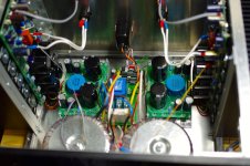
Your caps are installed correctly so it's most likely a problem with the output stage, with the power off, first thing to do is to measure the continuity between the heatsink and drain of the output FETs, anything less than open circuit is a leaky insulator.
If everything is ok so far, power the amp via a bulb tester, make one if you don't have one.
Next, short the base/emitter of Q13 & Q14 to ensure the output FETs are biased off, power up then measure to see if there is any voltage across the source resistors, if there is, you found your faulty FET(s).
Hi itsmee
Thanks for the help.
I get symmetrical low voltages. I have checked that the heat sink is not shorted to any of the output stages - no problem there.
I did wonder if I destroyed some fets with static.
I'll get on to Q13/14 tomorrow
Thanks for the help.
I get symmetrical low voltages. I have checked that the heat sink is not shorted to any of the output stages - no problem there.
I did wonder if I destroyed some fets with static.
I'll get on to Q13/14 tomorrow
With q13/14 shorted the light bulb throbs  So does the voltage across all the source resistors except 2. Looks like I need a new batch.
So does the voltage across all the source resistors except 2. Looks like I need a new batch.I must appologise, I'm an iddiot, it was a long hard day yesterday, I should put my brain in gear before typing. 
Shorting the base emitter of Q13/14 will turn the transistors off and therefor will develop a voltage across them; the transistors need to be fully turned on to bias the FETs off.
Short the collector/emitter of Q13/14 then measure across the drain resistors.
Forgot to mention, fit the feedback links into the local positions to prevent any interaction with the front end.
Last edited:
No worries itsmee
With the emitters and collectors shorted the voltage is back up to 24v. There's also 0v across all the source resistors. This is with local feedback.
With the emitters and collectors shorted the voltage is back up to 24v. There's also 0v across all the source resistors. This is with local feedback.
D'oh, you said you where using the FQA16N25C FQA12P20, these require about half the bias voltage, put an 8K2 in parallel with the 5K6 in the bias chain (base/collector of Q13/14) that should fix the problem.
Last edited:
With 8k2 everything is quiet and I have the 24v again. However, I can't get the mosfets to turn on. Should I try a higher value?
I have been more than a little foolish thinking I could simply use the fqa's.

I have been more than a little foolish thinking I could simply use the fqa's.
Last edited:
Yes, it looks like a little experimentation is needed.
A quick calculation shows that with the 8K2//5K6, adjusting VR3 (or VR4) you will get a bias voltage between 5 and 6 volts.
The original values (without the 8K2), the bias range is 8V to 9.5V
27K//5K6 should put you in the range of 6.7V to 8V which is probably where you need to be.
A quick calculation shows that with the 8K2//5K6, adjusting VR3 (or VR4) you will get a bias voltage between 5 and 6 volts.
The original values (without the 8K2), the bias range is 8V to 9.5V
27K//5K6 should put you in the range of 6.7V to 8V which is probably where you need to be.
Last edited:
Yippee 😀
I tried 15k first and was able to get some adjustment so went up to 22k. There's now correct settings all round.
Thanks so much itsmee.
Now for the other channel.
I tried 15k first and was able to get some adjustment so went up to 22k. There's now correct settings all round.
Thanks so much itsmee.
Now for the other channel.
Yes,
All fet UGS or F5X with current mirror.
I would like know if it is possible to use mosfet current mirror instead of bipolar
All fet UGS or F5X with current mirror.
I would like know if it is possible to use mosfet current mirror instead of bipolar
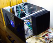
I finally powered up my UP today and played music. 😀
I completed the main amp boards over a year ago. Since then I have constructed the case and the VU board: albeit slowly.
Thanks go to Chef - what a fantastic amp and project. It sounds superb.
I'd also like to thank others that have helped. Particular thanks to Itsmee for letting me have his boards.
There are a couple of things to finish off before I post some pics. I need a nice shiny black piece of vinyl to cover the alu front. It will match my UGS pre too.
I also have a wait led illuminated which needs sorting.
I finally powered up my UP today and played music. 😀
I completed the main amp boards over a year ago. Since then I have constructed the case and the VU board: albeit slowly.
Thanks go to Chef - what a fantastic amp and project. It sounds superb.
I'd also like to thank others that have helped. Particular thanks to Itsmee for letting me have his boards.
There are a couple of things to finish off before I post some pics. I need a nice shiny black piece of vinyl to cover the alu front. It will match my UGS pre too.
I also have a wait led illuminated which needs sorting.
Congratulations it is indeed something special.
I'm curious as to what François is doing these days....
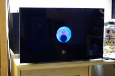
Looking good, have you listened to it yet?
I certainly have. It sounds superb 😀
...I would like know if it is possible to use mosfet current mirror instead of bipolar
The current mirror works from two matched bipolar transistors. The current (Ic and Ib) in one transistor is matched in the other by the bases seeing the same drive. MOSFETs ideally don't have gate current. 😉
- Home
- Amplifiers
- Pass Labs
- UGS Power : it's U.P.