Now there's something I understand, gonna be moving mine now.
Jim, I'd do bench work for you for free if I could just pick your brain a few times a day. Unfortunately (for me at least) we're at opposite ends of the states.
Jim, I'd do bench work for you for free if I could just pick your brain a few times a day. Unfortunately (for me at least) we're at opposite ends of the states.
Last edited:
Tesla jMcShane?
Jim,
Checked out your PS pic and wondering way to the right of it
where they bias is, are you taking a page from Tesla's note book?
How will that work with the little yellow antena wire?
Will it just pick up the voltage ala Tesla???
------------------------ JK above -------------------------------------
So over there on the left are the cl-90s? or cl50s?
I forgot which you recommended.
Now, wondering what you did differently to keep the
B+ lagging the bias supply?
Or
Do you run a separate non inrush wire back to
just one side of the primary (doubler source)
then use inruch limiter prior to the doubler diodes?
Well while I'm waiting for parts, I wanted to ask some questions about cosmetics. The bottom panel is covered in cigarette tar (almost a gold color) and the brown paint on the amp is in pretty bad shape. There's also a rust spot spot on one of the edges about 1" around. I REALLY don't want to lose all the screen printing or destroy the originality value of it. Is it really tough to get screen printing redone on a chassis like this? Is it a horrible thing to paint it a new color? (I'm more attracted to black audio equipment)
Thanks
I wanted to repeat CBOX's question about restoring the cosmetics of an old, beat up, Citation II. I've come across another Citation II that I'm thinking about restoring and I'm wondering if I should just bite the bullet and get everything (transformers and chassis) repainted and sacrifice the labels. Or is there a way of preserving the labels while still repainting?
Thanks,
---Gary
The govt has dumped so much power into the ionosphere over the past 10 years, "Superheating" it - Jims little yellow wire should power that citation for a good decade, and increase the output to 200WPC easily.
LOLz but half way serious.
They've beamed petajouls of power into the upper ionosphere over the past decade. Tesla wouldn't know what to do with his base station right now, would probably be glowing bright white by now.
Gary> What I'm trying to do is get a good scan of the Citation's lettering. I found out that it isn't EXTREMELY difficult or expensive to redo screen printing. All you need is a good, cleaned up scan of all of it, print the template out on transparency, and use a developer to imprint the image into the silk screen material. Let it develop, add paint, and off to the races! Nobody has uttered a word about preserving the "Turd" or painting it black... me and my partner have discussed doing it base coat black with clear coat and adding in some multi color LED's controlled ala Arduino. I'm already working towards making an arduino circuit to self bias the amp and making it able to maintain the AC balance on its own. I have already shopped around Ebay and found an OLED that will work PERFECTLY in the spot of the old gauge! Next just need to find a directional switch (UP down left right) that will fit in the place of the selector so that I don't have to drill out that hole. I would love some help with someone that knows arduinos and a little more knowledgeable about MOSFETS that could help me with this project.
Last edited:
Just for the record - that PS bracket was a customer's work, and until it is back in the amp not all the connections are made. The "yellow wire" is insulating tubing over some cap leads. He did a very nice job IMHO.
Jim,
So over there on the left are the cl-90s? or cl50s?
I forgot which you recommended.
I use CL-150s - I went through a lot of different numbers before I settled on those.
Now, wondering what you did differently to keep the
B+ lagging the bias supply?
Or
Do you run a separate non inrush wire back to
just one side of the primary (doubler source)
then use inruch limiter prior to the doubler diodes?
The limiters SLOW the B+ rush enough to stop the old "CLANNGGG!" noise that Cit II amps make as a surge of energy hits the power trafo and causes magenetostriction. The bias winding draws so little current that there's no similar phenomenon caused by it, so there is no need to slow/delay it at all.
Thee is no limiting added in the primary, just the 170 volt secondary. That's all it takes!
Cbox,
I've been watching this thread with interest.
I'd advise against your Arduino idea because this is a high bandwidth amp. Hence, it's VERY likely it will pick up noise from the Arduino if you cram it into the chassis.
Also, how are you planning on powering it? If you're going to be tapping off the Citation's power supply, you will be injecting noise from the Arduino back into the power supply. Ever wonder why high-end audio players run multiple power supplies? It's due to switching digital switching noise on the power supply bus...
Anyway, I doubt you'll listen, but figured I'd toss it out there for you to think about. The existing bias circuit has proven itself reliable for 50 years. Tubes don't need to be adjusted 50 times a second and I'd suggest doing so will only inject noise. It appears to me that you're still operating from the premise that current technology is better than "that old, outdated stuff." That's not necessarily the case. Things were done the way they were for a reason, and the circuits were finely tuned and optimized for their specific tasks. I used to think the same way as you, but have learned I was wrong. The guys that designed this stuff, especially in the late 60's near the end of the tube run, for the most part really, really knew their stuff. The technology was mature and much of the equipment was so well engineered that most of the new "current technology" can't hold a candle to it. There's an old saying that holds much truth - if it works, don't fix it!
If I were you, I'd be spending my time & money on the separate bias transformer setup that Jim recommends because it addresses a known failure mode.
On a different note, if that meter you removed is still good, I'd be interested in buying it if you're interested in parting with it.
Whatever you decide, good luck on your project!
Kind regards,
Steve
Last edited:
Cbox,
I'm going to add a couple more things for your consideration:
If the amp is not restored completely stock first and you haven't spent a fair amount of time listening to it, how will you know if any mods you do to it make it better or worse? At least if it's properly restored to a stock configuration first, you will have a benchmark to compare future changes against.
Food for thought.
Also to be clear, I'm NOT trying to rain on your parade. As I'm sure you know, you're working on something that is bordering on being unobtainium and it will become a boat anchor if you accidentally fry one of those transformers. While I admire your initiative, you might consider buying an inexpensive tube amp to perfect your computerized bias circuit before risking the good iron. You might even look for a broken tube guitar amp with similar outputs on your local Craigslist, fix it and use it as the guinea pig while figuring the bias control circuit out. Then, once the circuit has been perfected, transfer it to the Citation and spin the repaired guitar amp for a profit. The advantage being that if something doesn't work as planned during development and the magic smoke comes out, it won't be the magic smoke from your Citation.
Lastly, you might consider starting a new thread for the Arduino bias control development. There's a ton of expertise on this forum and it's likely someone else has already either done it or played with the idea. You'll get lots of help on figuring it out and it would receive significantly more exposure than having it buried in this thread.
http://www.diyaudio.com/forums/tubes-valves/170851-microcontrollers-tube-amps.html
http://www.diyaudio.com/forums/tubes-valves/233406-arduino-cathode-current-ht-etc.html
Steve
Last edited:
Thanks for the reply Steve... I didn't mean to over-exaggerate the tasks I wanted to assign to the arduino. I don't want the arduino to affect the audio portions of the circuit WHAT SO EVER. Stu did a HELLUVA job in designing this amp, from what I know about it currently. I don't think the old circuits are outdated or useless, but customization is what makes something "Your own" vs just another one.
Here's what I want the Arduino to do:
1. Operate a power button for the unit
2. Turn on the unit, supplying everything except B+
3. Turn on B+ when Bias supply is verified working
4. Shut down B+ and display an error if Bias supply voltage goes too low
5. Have a built in menu that will allow me to adjust the bias and AC balance (not constantly updating) but make it an automated OR manual process
6. Control LED illumination
As for the noise introduced into the amp, I was not aware of that. I could very easily do a 120v to 5v power supply completely separate from the amp. The circuit I would need is built into every single cell phone charger on the planet right now. Very easy to come by.
The Arduino plans are NOT happening right now, I'm just putting details together. Nothing Arduino will be soldered into the Citation for probably a GOOD while. You must remember, and Jim keeps reiterating: Some of the parts do not have good replacements. If I remember Jim correctly the Bias pots on the front of the machine do not have ANY direct replacements. I don't want to use technology to "Better" Stu's design, but rather to implement the things he did with a modern touch and replace these old (and RARE) pots with MOSFETs that no one will shrug about. Not to mention, losing the Bias supply can cause a lot of damage all on its own. Seems the Arduino might help PREVENT this thing from becoming a boat anchor given the right situation.
I will NOT be doing anything to the Citation's chassis that can't be reversed, except MAYBE drilling the LED's in. I will be looking for any alternative I can find first though. I love the concept of "Restomod" but I don't like the idea of modifying something so much that it's no longer capable of being original.
BTW Apologies but I won't be selling the meter...
I have a small 60v transformer already that I was using for bias supply. When I first got it running, I was using a separate transformer. With the Bias supply hooked up to the trans, the deuce would REALLY HUMMM when you turned it on and would blow fuses. Separating the Bias supply fixed that issue at the time. I hadn't rebuilt the bias supply yet either (didn't know enough about it to understand). Now that all the resistors are good, I'm optimistic that the factory transformer will be fine.
Cbox,
Sounds good and makes sense.
If you do shoehorn an Arduino in there at some point, you might think about encasing it in a metal box to try to minimize RF interference. With the amp bandwidth so wide, I'm just concerned that it might pick the computer noise right up.
You know, since you're looking at screening the print back on anyway if you paint it, why don't you just make a new chassis for it out of 5mm aluminum? I know it sounds extreme, but if you're already sanding and painting it anyway, it would allow you to easily install nice speaker jacks, LED, an IEC power connector, meter, etc wherever you wanted to.
Wouldn't be much more work than painting and screening the existing chassis and it would allow you to update the look and "make it yours."
If it does sound interesting, you might check out Front Panel Express. It would be easily make the panels if you went that way. Everything is cut using CNC and they can do little tiny text. Hence, wouldn't need to screen anything. All the holes would be drilled, the text cut in, etc... Kinda pricey, but their work is awesome. We use at work for research instruments we build and it really dresses stuff up.
They can do anything. I have been toying with having a couple of front panels made for my Citations because I can scan in the logo and have it cut into a piece of brushed 10mm plate and have it clear anodized. They will also paint if you want (or infill the text) but in that case they cut into clear anodized plate and brushing is not an option. Again, not cheap but it makes stuff look KILLER! Combine that with nice edges, brushing if wanted, and whatever color anodizing strikes your fancy, it would really update the look of the amp. The other option would be to alodine raw panels from them and then they would have the original gold color. Anyway, it's what I've been toying with..
No prob on the meter. I had to ask just in case it was going to end up in a box and forgotten about.
Again, I've been following your thread with interest. Stick with it, you're going to be VERY happy you did.
Most importantly, have fun!
Steve 🙂
I doubt the Citation will be my "End all-be all" amp. After college is over I want to build some different things as well. I actually looked at plans online for making your own torrid winding machine without spending much on the machine itself. Ideally one day I'd like to build an amp and transformers that perfectly match. (distant future) When I start looking into the plans to build it, there will be no holds barred. I don't want to build something 500wpc or anything ridiculous, maybe 120-150 but I want it to be GOOD. (the turd will be the yard stick I measure the new amp with, and I think that's ambitious enough) I was also reading Tubelab's posts and on his site about making a hybrid tube/solid state amp that was a miraculous performer! I was going to ask him for whatever details he has on it but he's in the middle of moving last time I saw him post. Its in the distant future anyway so I don't want to bother him while he's busy and my hands are full with college and the deuce.
Last edited:
The Citation 2 is arguably the best amplifier to come out of the classic period of hifi. IMO anyway.
I've had a number of them over the years. About 25 years ago I finally decided to see what would happen if I rebuilt not just the power supplies (which I always do with any older gear) but rebuilt the driver circuit using 12BH7s (or 6CG7s) instead of 12BY7s.
In so doing the sections of each tube were paralleled. I rebuilt the entire amplifier this way and used our custom wire (solid core copper with polyethylene foam jacket) as well as precision metal film resistors and polystyrene coupling caps.
The output section was left stock. I replaced the usual things like the RCA connections and the selenium rectifier. The amp ran fine and I never had a lick of trouble with it. I sold it to a local customer, who used it as his main amplifier for about 20 years. Recently I got it back and rebuilt the power supplies yet again, as the original rebuild was getting kinda old.
I'd be happy to post the schematic if anyone is interested. Obviously Jim is the expert on these amps (although back when I did the initial renovation the internet didn't even exist); for example although I have repaired a lot of these amps over the years (although mostly in the 1970s and 80s) I have never heard of the bias winding having a problem- food for thought!!
Atmosphere> I think it would be awesome, even if just for informational purposes. Who knows, it may become necessity for us in the future to abandon the 12BY7's as they become increasingly rare.
I'm having to take a break from the deuce for a few days. I have all my parts in, but I've gotten a little behind on school work. 🙁
I'm having to take a break from the deuce for a few days. I have all my parts in, but I've gotten a little behind on school work. 🙁
repainting and re-screening
Hi all
I'm also in the process of rebuilding a Citation II from the ground up. I did go to Jim McShane for the rebuild kits since his parts are well proven and his prices are really good.
But my post concerns the process of making it look as good as it will sound. My chassis is also pretty beat up. The aluminum needs some straightening, as does the steel in a couple spots, and the lettering is really tough to even see, let alone read. I decided to try repainting the chassis and transformers myself, then screen printing the lettering on using gold metallic printing ink. I went to a local (Mesa, AZ) auto paint store and bought some base coat and clear coat. I also got some equipment and chemicals to do the printing as well. I have already scanned the chassis parts to get a full size image, and then processed them with GIMP freeware to get correct sized templates. (BTW, if anyone want the pdfs let me know and I'll post them. As I progress I would be happy to post some pics. I won't be getting it to the painting until some time next week, so it will be awhile before pics come out.
Bill
Hey Bill... if you got some good clean scans of all the lettering, please do share those PDF's! That will save some of us a few hours fighting with the scanner 🙂
pdf scans and templates
I will post when I get back to my audio office next week. I will make some reduced size pics of the actual scans so you can see what Iim starting out with, and then I'll post the actual size post-image-processed pdf templates that I'll use in the screening process.
I will post when I get back to my audio office next week. I will make some reduced size pics of the actual scans so you can see what Iim starting out with, and then I'll post the actual size post-image-processed pdf templates that I'll use in the screening process.
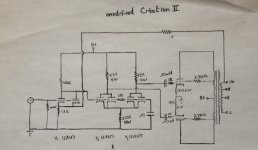
This is the basic schematic. As you can see its the same topology, but executed with triodes. The schematic indicates 12AU7s but you can use 12BH7s just as well. Things that were not changed from the original amp are not shown- the biasing setup is an example.
As you can see there are not 3 feedback loops but one. While the amp sounds fine, these days I question the amount of feedback (6 db), as lower amounts of feedback can be risky in some designs. Since the triodes are so much more linear it did not seem to be helpful to run feedback around them, especially since this circuit has less gain overall.
If I were to do this again, I would readjust the plate values of the driver section as it clearly is doing no good to have them be equal due to the cathode coupling/mu issue. I would also consider a 2-stage CCS for the circuit.
Attachments
Last edited:
Thanks for your time Ralph.........Looks like a vary clean setup like most of your work....
.i gess the PS is HK stock....just upgreaded parts?
Also i have been playing with some GE,RCAs 12AT7....in place of my 12au7.....I know you use the AT in your pramps an as driver in one OTLs....this tube is new to me....
I have been hooket on the 6SN7 an 6AS7....an the AU7,BH7 for 25years...
Got get back to a 6AS7 preamp like you had at one time......what B+ do you run your AT plats at..................?
I set up the Citation supply to be stock, with slightly greater capacitance.
We've not used 12AT7s as driver tubes in quite some time. Usually its 12AU7s or 6SN7s. The power supplies for the 12AT7s never exceed 300V and in the preamp they are more like 250V.
We've not used 12AT7s as driver tubes in quite some time. Usually its 12AU7s or 6SN7s. The power supplies for the 12AT7s never exceed 300V and in the preamp they are more like 250V.
I did some work on a pr of VTL 100s .....an got looking at all the amps an preamps an saw thay only use the 12AT7s? .....An the ATs do have a sweetnes to them.....better bass an mid than the AUs......well to day thay do.......as a output driver in my old hhscott 355 pretuner....that runs the Left an Right output thought one tube.............
thanks
thanks
- Home
- Amplifiers
- Tubes / Valves
- Harman Kardon Citation II - rebuild questions