For now...the resistor in series with the collector of the first transistor.
There's a few subtleties with this.
If you haven't already you should read Samuel's comments HERE on the way to use the first transistor base current to balance the current mirror.
What he doesn't discuss is that as a series resistor is added, this reduces the hFE of the transistor (by Early effect.)
This can help you balance the mirror because the thermal properties of the first transistor will better track the mirror transistors (they don't have much Vce drop and will not dissipate much power).
Also it provides a delicate way to trim the current balance, because a substantial decrease in Vce will have only a smallish effect on base current.
The reduced hFE will reduce the return ratio, which will usually help stabilize the circuit too, unless you have complicated compensation.
But the hFE can be reduced to the point that the distortion suffers.
It is possible to decouple the resistor with a capacitor to keep the DC balance but recapture some of the return ratio, probably worth a check if you really want to optimise the circuit.
Best wishes
David
Last edited:
Is post13 the same as you...
Is it Q7 that you are...
I understand the OP's idea is to limit the current in Q7 of post #13 and that this will help protect the VAS transistor too.
Retrofitted in an Australian published amp a few years back, Silicon Chip I think, after an overload blew the prototype.
But they didn't discuss the side effects, so I wanted to point out the less obvious aspects.
Best wishes
David
Last edited:
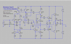
I tried the circuit in post 13 but suffered oscillation of the negative peak during negative clipping (real circuit). The other method I'm currently using is, if we use the circuit of post 13... delete Q15, R27 and R26 and add 4K3 into the collector leg of Q7. The transistor I'm trying to protect is Q8. This is during clipping when Q7 drives it hard to compensate for the negative clip.
Did you try the values and circuit configuration in post #15 ?
I never remember any problems driving the amp into clipping but I never tested it into a low impedance load. As long as any oscillation is non destructive and the transistor is protected with nothing latching up then there probably isn't a problem in practice. Oscillating or not, you are not going to be listening to it operating in the region where it clips.
I never remember any problems driving the amp into clipping but I never tested it into a low impedance load. As long as any oscillation is non destructive and the transistor is protected with nothing latching up then there probably isn't a problem in practice. Oscillating or not, you are not going to be listening to it operating in the region where it clips.
Could some of you describe the mechanism of what happens and where the currents flow during a clipping sequence?
Could some of you describe the mechanism of what happens and where the currents flow during a clipping sequence?
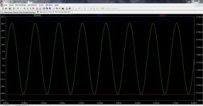
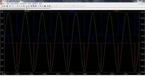
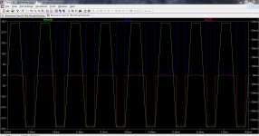
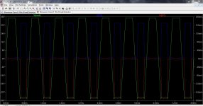
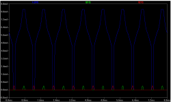
Easy to see in a sim. This is with no load. Notice how little the clipping is in the second image and yet how large the peak VAS and its driver current become. Final image is major clipping.
And this is with the limiter in place.
Attachments
Increase VAS emitor resistor (R26?) about 4 x..And remove Q15. Try simulation wit added diodes, as posted above.
Last edited:
Increase VAS emitor resistor about 4 x..
The VAS will just limit at around 0.7/R so around 15 ma for a 48 ohm emitter resistor. The driver for the VAS still sees quite a large current (relatively speaking) of around half that.
looks like both the VAS and it's EF need current limiting.
Q7 is easy. Just add a resistor between collector and ground.
With 1k in the emitter lead, add a 1k in the collector lead, will limit the maximum total power in {Q7+resistors} to Vrail^2 / [1k+1k]*2
for a 50Vrail that comes to 5-^2 / 4k = 625mW.
Half is dissipated in the resistors and the other half in Q7. i.e. Q7 never sees more than 312mW and this as a transient not continuous.
If the emitter resistor were a bit lower, then increase the collector resistor to make the "Total dissipation" an acceptable value.
A few more sims would be appreciated.
I'm told that the collector resistor increases distortion slightly. How slightly?
Last edited:
Those are the currents predicted by the sims.
Please explain the scenario that leads to these currents.
What initiates the destruction?
Does it start with the LTP pulling all the tail current through only one half of the pair?
Please explain the scenario that leads to these currents.
What initiates the destruction?
Does it start with the LTP pulling all the tail current through only one half of the pair?
2 Mooly
Can You post .asc file?
I will do it now.
Those are the currents predicted by the sims.
Please explain the scenario that leads to these currents.
What initiates the destruction?
Does it start with the LTP pulling all the tail current through only one half of the pair?
That should work although you would need to check if it affects distortion under load etc.
Mis-read the mA scaleI will do it now.
That should work although you would need to check if it affects distortion under load etc.
changed values to correspond.
post28 pic1 shows the collector current of Q7 ~0.9mA.
A 1k in the collector would move the collector voltage from ground to -0.9Vdc.
Q7 now has 48.2Vce whereas without the extra resistor it had 49.1Vce.
Last edited:
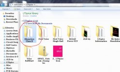
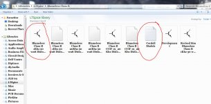
What do I do to get it to run?
It asks for Cordell model.
Put the two files into the same location. You can either make a new folder or use any existing folder you have on your PC.
Are you on W7 ?
Attachments
- Status
- Not open for further replies.
- Home
- Amplifiers
- Solid State
- VAS current limit for Blameless Amp