Hi,
i have many doubts about wiring the secondaries in a mains voltage transformer
If i have 4 terminals marked: V, 0, V and 0 like the one in the picture

to get the center tap (i.e. V-0-V) at the output which terminals i must connect ?
i assume the two 0 terminals together ... am i wrong ?
If i want to wire in parallel the 2 sec i think i will have to connect the two V and the two 0 together
But to wire them in series ? i think the 0 of one secondary with the V of the other ... am i right ?
Last question ... if i have a transformer with 2 sec without any indication of V and 0 terminals ... is there a way to establish which is which easily ?
Thanks a lot and kind regards, gino
i have many doubts about wiring the secondaries in a mains voltage transformer
If i have 4 terminals marked: V, 0, V and 0 like the one in the picture
to get the center tap (i.e. V-0-V) at the output which terminals i must connect ?
i assume the two 0 terminals together ... am i wrong ?
If i want to wire in parallel the 2 sec i think i will have to connect the two V and the two 0 together
But to wire them in series ? i think the 0 of one secondary with the V of the other ... am i right ?
Last question ... if i have a transformer with 2 sec without any indication of V and 0 terminals ... is there a way to establish which is which easily ?
Thanks a lot and kind regards, gino
Last edited:
To wire in series (and get CT) connect one 0 to one V.
To wire in parallel connect 0 to 0 and V to V.
If unmarked proceed with caution! You first need to identify the primary.
Never connect secondaries in parallel until you have identified them. Connect in series (as above) and measure total voltage. If double one secondary then correct. If very small then reverse one of them.
In any case when messing with mains transformer always use a lamp limiter.
The bulb tester saves damage to the transformer, no matter how badly you wire up the primaries and/or secondaries.
To wire in series (and get CT) connect one 0 to one V.
To wire in parallel connect 0 to 0 and V to V.
Thanks a lot indeed. I was clearly thinking wrong to get the CT.
And i found also a picture showing what you say now
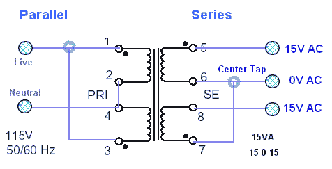
I wonder what will happen if I connect the two 0 sec terminals 6 and 8 together Will I not get a CT as well ?
I was so confused that i have always bought transformers with just 2 terminals at primary and 3 terminals (V-0-V) at the secondaries, to avoid any mistake.
If unmarked proceed with caution! You first need to identify the primary.
I think i expressed badly myself.
I mean that some manufactures miss to print 0 and V on the secondaries terminals
There are different colours but sometimes the terminals are difficult to indentify correctly.
Usually the primary instead is clearly indicated
I understand that if i connect the mains to secondaries is a disaster ...
Never connect secondaries in parallel until you have identified them.
Connect in series (as above) and measure total voltage.
If double one secondary then correct.
If very small then reverse one of them.
In any case when messing with mains transformer always use a lamp limiter
Thanks a lot for the precious advice. I did not even know about the existance of this lamp limiter.
This 0 and V thing has always confused me a lot indeed.
At the point that i have always bought transformers with 3 terminals output
Thanks again, gino
Last edited:
Always good to have a set minimum to the load connected to mains. It can be unforgiving. The series light bulb is a reliable safety net. A light bulb (incandescence) has a low resistance when cold but increases significantly when hot. If wiring after the bulb in the circuit is shorted, the bulb lights up, dropping the mains voltage and nothing burns. If little current is taken by the transformer, the bulb is cold and the primary will then see the mains voltage.🙂
If ever in doubt, use a light bulb. 😉
If ever in doubt, use a light bulb. 😉
Hi,
Its confusing, connecting the OV's in post#1 does not
give a centertap. Note one winding is reversed in post #4.
Connecting 6 and 8 is the same as the OV's,
the two secondaries are parallel and in phase,
and you may as well connect 5 and 7 also.
rgds, sreten.
If you have an unknown 3 wire secondary, measure DCR
between all 3 pairs of wires. One pair should measure
twice the other two pairs. The other wire is the CT.
Last edited:
Always good to have a set minimum to the load connected to mains. It can be unforgiving. The series light bulb is a reliable safety net. A light bulb (incandescence) has a low resistance when cold but increases significantly when hot. If wiring after the bulb in the circuit is shorted, the bulb lights up, dropping the mains voltage and nothing burns. If little current is taken by the transformer, the bulb is cold and the primary will then see the mains voltage.🙂
If ever in doubt, use a light bulb. 😉
Thanks and sorry but i am slow to catch up
You mean that if i put a light bulb in series with my body i will be safe ?
Must it be on the live wire of the mains ?
Thanks again, gino
Hi, Its confusing, connecting the OV's in post#1 does not give a centertap.
Note one winding is reversed in post #4.
Connecting 6 and 8 is the same as the OV's, the two secondaries are parallel and in phase, and you may as well connect 5 and 7 also.
rgds, sreten.
Hi and Thanks for the valuable explanation
If you have an unknown 3 wire secondary, measure DCR
between all 3 pairs of wires. One pair should measure
twice the other two pairs. The other wire is the CT
This is clear and it is the reason why i much prefer a 3 output terminals transformer (usually they are also marked V-0-V )
Lately my obsession has moved from capacitors to transformers
I think that a good transformer can indeed change the performance of an equipment in a remarkable way
I have to study more as usual
Thanks again, gino
You mean that if i put a light bulb in series with my body i will be safe ?
Errr no 😱

Must it be on the live wire of the mains ?
The bulb, yes. Not you. And it must be a filament bulb, not an energy saver type.
What?!?You mean that if i put a light bulb in series with my body i will be safe ?
No, place the light bulb in series with the primary, or whatever load is connected to mains. It is to limit the current flow possible to the load. Your body and mains are not meant for one another. IOW, line to one side of bulb, other side of bulb to switch, then switch to transformer primary, then primary to neutral.
Perhaps there is a language barrier, but if you have to ask about placing your body into contact with anything having a mains voltage connection, then should you be playing around with mains voltage source?

Hello and thanks to both of You for saving me to do something very wrong 😱
Now i understand ... the bulb must be wired in series with the primary to limit the current entering the transformer ... ok !
And i have also to check that the bulb is on the live line and not the ground line i understand.
I could use a mains tester for that.
I think that i should reallt work with some kind of very effective life saver near the experimental desk ... something absolutely sure.
Like a distribution panel ...
I have to do a search ... like a power distribution bar (i.e. power strip) with a lifesaver device in it better be safe then sorry ...
This will be my first buy.
Thanks again and kind regards, gino
You could use a 230:230 isolating transformer. That will keep the Mains voltage away from prying hands and tools.
You could use a RCCB on the Mains feed to detect current that returns to power company by any route than through the Neutral.
You could use an RCCB on the output of the Isolating transformer to detect current that returns to the isolated secondary via the "floating" work bench "Earth".
Both the mains feed and the secondary output should be fused. Fuses or MCBs.
Comments from electricians please !!!!!!!
Transformer Information
Here's a thought.
If you do'n't know what transformer you have, then the following might be useful!
When you are trying to identify an unknown transformer you should use the following procedure.
1) Identify the HIGHEST impedance/resistance winding. Even the most basic of multimeters can do this. 2) From a KNOWN transformer, connect the low-voltage secondary to the winding identified above. (This isolates the transformer, and yourself, from painful mains contact) 3) Using your multimeter you will then be able to identify the windings and their voltages.
{We use 240v over here so using a 24v transformer gives a direct 1:10 ratio} ie. if you measure 24V then, when connected correctly, will be 240V.
The light bulb in series with the primary of your known transformer is a VERY good idea -
Here's a thought.
If you do'n't know what transformer you have, then the following might be useful! ... The light bulb in series with the primary of your known transformer is a VERY good idea -
Hi and thanks a lot for the valuable advice
But i have decided to buy only transformers accompanied by a complete datasheet with specs
I do not buy a lot of them. Better to stick with a famous brand like Talema
And usually they provide all kind of information
Thanks and regards, gino
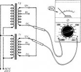
Hi and just to say that it took me a while but i have found a picture that explains that i will have also to respect the phase when connecting in series the secondaries of a transformer
This one
So there is only one way to connect rightly the secondaries in series, easily tested with a meter
Issue definitely close. Thanks to all.
Kind regards, gino
This one
So there is only one way to connect rightly the secondaries in series, easily tested with a meter
Issue definitely close. Thanks to all.
Kind regards, gino
Attachments
Last edited:
and you only do this test with aprimary fuse fitted that is small enough to protect a shorted primary apir or a shorted secondary p[air.
You should preferably test when fed through a mains bulb tester as well as the close rated fuse.
You should preferably test when fed through a mains bulb tester as well as the close rated fuse.
and you only do this test with aprimary fuse fitted that is small enough to protect a shorted primary apir or a shorted secondary p[air.
Hi and thanks for the kind advice.
If the transformer is around 600VA what would be a good value for the fuse with 230 V on the primary ?
It is a transformer with one primary and two secondaries.
The secondaries are quite thick indeed and this i like very much.
The primary would be 0.5 mm diameter. Thin ...
You should preferably test when fed through a mains bulb tester as well as the close rated fuse
I have already tested the quality of the circuit breaker in my flat
With the transformer connected there was a short in the amp
I sincerely hope it is not in the transformer
But i would like to build a power strip with a safety breaker upstream.
So that i could work with tranquillity.
Here we have schuko plugs ... so it is possible to exchange L with N and this could be dangerous i suppose.
Thanks again, gino
A single primary cannot be wired "out of phase". that solves the first and biggest problem.
A dual secondary can be wired "out of phase". That problem can damage a transformer, even when the amplifier is not connected.
A close rated fuse is VA/Vac, for a 600VA transformer on 220Vac, use a T2.5A or T3.1A
For initial testing with the bulb tester (try 40W bulb) in the primary circuit you can probably work with T1A.
When you have proved your final assembly and time to remove the bulb tester you will need a soft start circuit, or change to a T8A fuse which is too slow to protect anything.
0.5mm primary wire is very thin for a 600VA transformer.
The current rating of 0.5mm diameter is usually taken as 3.1*D²*Pi/4 = 0.6A That gives a Primary VA rating of 134VA for a 220Vac supply.
The output VA would be ~95% i.e. ~127VA
I would expect Primary wire of a 600VA to be 1mm to 1.2mm diameter.
Last edited:
All these basic question raises the same questions in my head as are being raised in others. Are you out of your depth?
What have you learned in your own research?
What have you learned in your own research?
A single primary cannot be wired "out of phase". that solves the first and biggest problem.
A dual secondary can be wired "out of phase". That problem can damage a transformer, even when the amplifier is not connected.
Hi and thanks and this is of course my main problem
To avoid of hurting myself and damaging the component.
For this i am always more comfortable with center tap transformers, i mean a transformer with 3 output: V-0-V. End of the story. No problem at all.
When i get an unknown transformer i have always the problem to form this damned CT
And now i understand that if i connect them badly i could ruin the transformer
So the problem remains how to connect rightly the secondaries in order to get the CT
I have not been able to understand how to this
A close rated fuse is VA/Vac, for a 600VA transformer on 220Vac, use a T2.5A or T3.1A
For initial testing with the bulb tester (try 40W bulb) in the primary circuit you can probably work with T1A.
When you have proved your final assembly and time to remove the bulb tester you will need a soft start circuit, or change to a T8A fuse which is too slow to protect anything.
Even this is a problem because the plug can be reversed
So the bulb could be on the Live line or the Neutral depending how the plug is placed
Not so with US plug i understand but with Schuko plug the problem exists
i think everything is going to the garbage bin0.5mm primary wire is very thin for a 600VA transformer.
I thought it was a commercial unit instead is a bd DIY realization
It happens when you buy without lifting the lid
The current rating of 0.5mm diameter is usually taken as 3.1*D²*Pi/4 = 0.6A That gives a Primary VA rating of 134VA for a 220Vac supply.
The output VA would be ~95% i.e. ~127VA
I would expect Primary wire of a 600VA to be 1mm to 1.2mm diameter.
Thank you very much indeed and these are the rules i was talking about
Just measuring with a caliber the diameters of the leads some very important considerations on the limits of a transformer can be made
Strangely enough instead the secondaries are very thick ... good.
Unfortunately the primary is really thin and also for this it will end in the garbage bin,
Just to sum up ... so
1) if i have 2 secondaries to get the CT i have to respect the phase ?
2) How can i check the phase in the secondaries ?
I want only to form this bloody CT ... 🙁🙁🙁 in the end
Thanks a lot again, gino
Last edited:
- Status
- Not open for further replies.
- Home
- Amplifiers
- Power Supplies
- Some basic questions on transformer with two secondaries