Remember, Terry is working with a compromise of an IPS to start playing with things. We don't know how 'stiff' his +/-77V supply is either, so he may not be realizing the full potential. Also, OS is fond of teasing us with quoting into 4R, Terry is using 8R. 210W average into 8R isn't too shabby for something that is currently a patchwork test fixture.
OK so if I'm understanding this correctly, the input filter on mine is 10K/470pf. Lazy Cat is suggesting 560 Ohm/100 pF. Is this correct?
No, it is the 1K6 (R4) and the 470pF (C2), make R4 560R and C2 100pF. The 10K provides input bias current and sets the input impedance.
Terry,
210 watts with five pairs of outputs? That doesn't sound like what OS is quoting?
I stated the 5-pair estimate at the max 85V.
I figured 250/500 (8/4R). You could even push things to 90V with
semelab outputs.
As a reference , the HK990 ... with 5 pair and 72V rails , is quite
conservatively rated at 150/300 😱 .
I ran this amp into a 4R sub at >400w for 10 minutes to test the
cooling servo ! 😀
PS - 210 is not bad with "jury rigged" IPS's ... the "real" IPS(any of them) will
really fly - I promise ! 🙂
EDIT - keep in mind that with the hawksford/multipliers/EF3 , you can lose >7 V
from the rails. This amp is meant for very high voltages.
OS
Last edited:

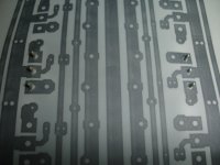
Just get rid of the unmasked star point. OV can be the test point.
Heatsink can be one piece again.
Excellent work.
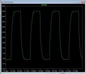
ps - bet you could get this board to put out nice 400K SW's !
(just to push the limits)...
edit - EASY ... even 1mhz still looks "square" 😀 .
OS
Heatsink can be one piece again.
Excellent work.
ps - bet you could get this board to put out nice 400K SW's !
(just to push the limits)...
edit - EASY ... even 1mhz still looks "square" 😀 .
OS
Attachments
Last edited:
As for a proper IPS, I submit this for someone (ahem, OS? care to take a look?) to check for any errors. This would be the CFA-XH v1.3
JK
I like your work.
i m waiting to finish IPS and i get both IPS and SLEW MONSTER 5P
I like your character shown in the forum, everything in life is not electronics.
Nikos.
slewmaster
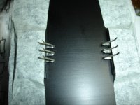
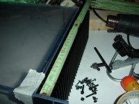
I want to mount two pairs MT200 transistors on this heatsink.(SA56/100SA)
It's useful if i have some opinions about this way.
Thimios.
I want to mount two pairs MT200 transistors on this heatsink.(SA56/100SA)
It's useful if i have some opinions about this way.
Thimios.
Attachments

Last edited:
I want to mount two pairs MT200 transistors on this heatsink.(SA56/100SA)
It's useful if i have some opinions about this way.
Thimios.
I think, If you can mount VBE multiplier transistor on main heat sink without cables, it is OK.
Just get rid of the unmasked star point. OV can be the test point.
Heatsink can be one piece again.
Excellent work.
ps - bet you could get this board to put out nice 400K SW's !
(just to push the limits)...
edit - EASY ... even 1mhz still looks "square" 😀 .
OS
I only broke the heat sink line to avoid a DRC error (silk on pad), the intent would be of course for the heat sink to be one piece. The main reason to keep the silk off that pad was so a spot of solder could be added to mechanically reinforce the via connecting the top and bottom. I followed parts placement fairly close to your example, including the IPS 'star' point, so I'm not sure what you mean by getting rid of the unmasked star point. Can you clarify your thoughts?
JK
I like your work.
i m waiting to finish IPS and i get both IPS and SLEW MONSTER 5P
I like your character shown in the forum, everything in life is not electronics.
Nikos.
Thanks for the kind words Nikos.
I only broke the heat sink line to avoid a DRC error (silk on pad), the intent would be of course for the heat sink to be one piece. The main reason to keep the silk off that pad was so a spot of solder could be added to mechanically reinforce the via connecting the top and bottom. I followed parts placement fairly close to your example, including the IPS 'star' point, so I'm not sure what you mean by getting rid of the unmasked star point. Can you clarify your thoughts?
The "badger" layout has a few through- holes that are masked on both sides.
On my layout I had the star point offset (away from the heatsink).
I suppose it would not matter.
OS
Testing -3db (high bandwidth).
Tested at 10vRMS/4R
CFA-X V1.3 150KHz.
CFA 1.2 158KHz
Gnome 158KHz
Spooky 154KHz
Symasui 150KHz
Thimios.
Tested at 10vRMS/4R
CFA-X V1.3 150KHz.
CFA 1.2 158KHz
Gnome 158KHz
Spooky 154KHz
Symasui 150KHz
Thimios.
Testing -3db (high bandwidth).
Tested at 10vRMS/4R
CFA-X V1.3 150KHz.
CFA 1.2 158KHz
Gnome 158KHz
Spooky 154KHz
Symasui 150KHz
Thimios.
Hi Thimios,
Did you measure with the input HF filter in place (I mean 100pF cap, grounding the input at HF)?
Hi vzaichenko,unfortunately yes so i must repeat these measurements.Hi Thimios,
Did you measure with the input HF filter in place (I mean 100pF cap, grounding the input at HF)?
Thimios.
Hi vzaichenko,unfortunately yes so i must repeat these measurements.
Thimios.
Right, that's what I thought seeing roughly equal bandwidth of 150 kHz, significantly influenced by that filter...
OK, fresh back from testing some of my other amps. Surprisingly, or maybe not, the purest looking 100K square wave was the Ovation NX. The 100K wave looked about like the 20K wave does above. I checked the Fetzilla, SKA GB150, DX Super A, DX MKIII, And Ovation nx. The squarest was the Super A but it has an overshoot and blew a fuse while I was testing. The MKIII was fairly square but tilted in on both sides. The FetZilla had bad squiggly lines as did the GB150. May have some oscillation I didn't know about. To be honest, I never tested any of my amps above 20K before. Didn't think it mattered. This Slewmaster concept is going to teach me a lot, I can see that now.
Blessings, Terry
Terry, I wonder how much of this difference is due to difference in input filter?
Jan
Terry, I wonder how much of this difference is due to difference in input filter?
Jan
As he always claims that there's really not much of the difference among them (his DIY amplifiers), I suppose an excessive input filter has much of the role here. 🙄
Test repeated.Right, that's what I thought seeing roughly equal bandwidth of 150 kHz, significantly influenced by that filter...
New measurements,the problem isn't input filter but generators out voltage which isn't stable when frequency changes.
-3db high .All these tested at 10VRMS/4R
NAD V1.2 / 445KHz
Spooky / 400KHz
Symasui / 400KHz
CFA-XV1.3 / 315KHz
CFA V1.2 / 322KHz
The rest of test later
PS THE BEST LOOKING SINUSOIDAL at 400 khz belongs to Spooky
Thimios.
Last edited:
As he always claims that there's really not much of the difference among them (his DIY amplifiers), I suppose an excessive input filter has much of the role here. 🙄
Actually, what I always claim is that there is not a lot of difference in the way they sound when pitted against each other with the volume is equalized. I must say I was quite surprised how much difference I saw yesterday when I played that 100k square waves through them. No two were alike and some looked dreadful. I'm still not sure how much the way an amp plays a 100k square wave affects what we hear. After blowing fuses on my Super A, I'm not sure how anxious I am to continue the practice. Seems it's hard on the components.
On this new CFA, I changed the input filter to the 560R/100p and there is only a very slight change. I wonder if that big 10uf film cap is affecting it. I will try jumping it today and see if that changes things. I'm not in love with the way this amp sounds. There is still a little too much upper mids. The snare doesn't sit nice in the mix and vocal affects are emphasized. We'll see if bypassing the input cap will improve things. Looking forward to building some more IPS's.
Blessings, Terry
- Home
- Amplifiers
- Solid State
- Slewmaster - CFA vs. VFA "Rumble"