Hopefully, moving on toward the present, I did find the cap measurement papers from HFN in 1985, and guess what?
Cap vibration sensitivity is important, and many well known caps tend to fail this test.
Now, the testers of 1985 used a commercial accelerometer to note the vibration pattern of a pulsed cap, is there an easier alternative that could be used today? An alternate, perhaps solid state accelerometer, or even a phono cartridge? I think that the phono cartridge is something that I can try fairly easily. Any suggestions, fellow engineers?
Why bother putting an accelerometer on the cap? What's that going to tell you that's meaningful? I thought the whole point was to see what happens to the signal passing through the cap?
se
se
SE,
That was what I was thinking. Is the small acoustic emissivity of a cap really important in the least, isn't it what you are doing to the signal that we want to know about. Now I could see if you really wanted to know what the effect of different modulations of the signal by acoustic coupling could cause to the signal but how would you measure that by measuring the vibration of the physical component? I guess if you truly had a component that was making a sound loud enough to be heard you would surely want to remove that device and substitute one that did not do that, but to what other reason is this relevant?
That was what I was thinking. Is the small acoustic emissivity of a cap really important in the least, isn't it what you are doing to the signal that we want to know about. Now I could see if you really wanted to know what the effect of different modulations of the signal by acoustic coupling could cause to the signal but how would you measure that by measuring the vibration of the physical component? I guess if you truly had a component that was making a sound loud enough to be heard you would surely want to remove that device and substitute one that did not do that, but to what other reason is this relevant?
Yea. JC's phrasing seems to mix 2 phenomena :Why bother putting an accelerometer on the cap? What's that going to tell you that's meaningful? I thought the whole point was to see what happens to the signal passing through the cap?
se
1) cap vibrates when passing AC (accelerometer apt)
2) cap produces AC when vibrated (scope and speaker ?)
Scott, I might agree with you that the 1741S (now that it is recognized as actually existing) was a short term solution to a real problem, i.e. how do you get a good slew-rate out of a process that can only make the equivalent of 741's normally? I think it is a brilliant, but flawed solution to the problem, 40 or more years ago.
In principle, why can't modern op amps utilize a similar technique? Then perhaps 20V/us might become 200V/us or even more, and with the now significant change in the rest of the topology or processing? This (breakthrough) would create a new improved IC and complete the process of design to phase 3. You know: you invented it. '-)
I already told everyone twice why slew enhancement is a dead end, I gather you pay no attention to what the other side says. We are beyond 11,000V/us where have you been?
Scott W suggested the cartridge idea a few days ago. Use a cheap one!!!
Lots of us probably have an old M91E or $15 Grado around somewhere, don't forget to account for the equalization differences between phono/accelerometer.
Last edited:
George
Pavel thank you for answering.
I haven’t seen again an amp behaviour as this.
What I knew was that the pole frequency moves lower when an OPA's or INA's gain is increased (ditto for increasing the comp capacitor)
I need to do some reading.
Regards
George
Last edited:
Yes, a job for the next generation of designers. A careful read will show some bypassing tricks and some interesting distortion differences due to supply current modulation in the bond wires, the kids learned well.
No engineers here, just bloody amateurs.....Any suggestions, fellow engineers?
Last edited:
don't forget the current noise and 1/f noise corner
the ADA4898 has better spec there and the +/-15 supply - even if only 65 MHz and distortion higher above audio - consequence of conventional ps pin layout?
+/-5 Vs isn't as big a limitation in today's digital audio world with 1-2 Vrms consumer level, and of course multiloop with a output stage that swings higher would cut possible thermal effects that might exist at audio
Last edited:
I tried ADA4898 several years ago and I have recently placed it in my last preamp - it is a very good part.
ADA4899 tested for audio as well - perfect part (yes 1/f corner is higher), +/-6V is a limitation. I guess it is so good (for audio) for the reason that because ot the high speed it has no problems with HF interferences.
P.S.: John might appreciate that ADA4899 OLG corner is at 20kHz = flat OLG at audio band.
Last edited:
Engineers can be amateur audio designers, and still be good engineers in their field of specialty. It is only when engineers, who do not normally design audio equipment, start making comments about audio designs that do not fit the experience of audio designers.
SE,
That was what I was thinking. Is the small acoustic emissivity of a cap really important in the least, isn't it what you are doing to the signal that we want to know about. Now I could see if you really wanted to know what the effect of different modulations of the signal by acoustic coupling could cause to the signal but how would you measure that by measuring the vibration of the physical component? I guess if you truly had a component that was making a sound loud enough to be heard you would surely want to remove that device and substitute one that did not do that, but to what other reason is this relevant?
Its been done. There was a study presented to the AES years ago by a UK capacitor manufacturer. They used something like a laser inferometer to detect the mechanical changes in dimension of a film cap under current.
Easy to measure with the sensitive equipment they had, but as I remember, the peak excursion was on the order of magnitude of the molecule size of the cap foil material.
Jan
Thanks Jan.
I assume you can measure just about anything if you know what you are looking for. But simply putting a cartridge stylus on a capacitor to measure physical movement seemed a silly application for a test. Sort of like wondering how high a tire would bounce if you dropped it off a cliff, wouldn't have much relevance to how well it would roll down the road, though you could measure its rubber compounds for traction and resistance to rolling with other suitable testing. Understanding what you are looking for seems to be appropriate to setting up any test protocol.
I assume you can measure just about anything if you know what you are looking for. But simply putting a cartridge stylus on a capacitor to measure physical movement seemed a silly application for a test. Sort of like wondering how high a tire would bounce if you dropped it off a cliff, wouldn't have much relevance to how well it would roll down the road, though you could measure its rubber compounds for traction and resistance to rolling with other suitable testing. Understanding what you are looking for seems to be appropriate to setting up any test protocol.
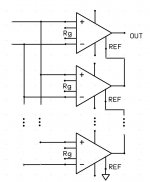
There have been a couple of mentions of paralleling amplifiers for low noise test measurements. Before I forget this old idea still has merit. IC instrumentation amplifiers can be paralleled and their outputs combined with no extra components. The SSM2219, THAT1512 would both work here (unfortunately the outputs only add so so 4 parallel G =1000 amps would have G = 4000 but <.5nV noise). The best candidate is the new AD8229 which has 1nV RTI noise at a lower closed-loop gain. The 210C version of the AD8229 is for oil well exploration and has a price to match, there is now a plastic version.
You can also stack in two groups with inputs cross-coupled and get diff-in diff-out.
You can also stack in two groups with inputs cross-coupled and get diff-in diff-out.
Attachments
Last edited:
- Status
- Not open for further replies.
- Home
- Member Areas
- The Lounge
- John Curl's Blowtorch preamplifier part II